Table of Contents
Electronics Basics
.
In order to understand better electronics, some basics in electricity are needed.
1 - Basics of Electricity
In order to explain electricity, let's imagine a waterfall. A stream going from where there is something to where there is not. Electricity is the same, it's a stream of positive charges going from + to -. (Since the electrons themselves are negatively charged, they move from - to +; but the subtlety of this only matters in semiconductor design.)

But let's stay on the waterfall:
- The electricity equivalent to the Volume of water dropping is called Current ( the quantity of electrons which are moving)
- The electricity equivalent to the Height of the waterfall is called Voltage ( the energy of each electron).
If we want to calculate the power of our water stream we will have to take volume and height in consideration, which gives us: Power = Volume x Height
Let's transpose it to electricity, it gives us : Power = Voltage x Current , so in electric units :
Watts = Volts x Amperes
.
2 - Ohm's Law
If we put some rocks in the water before it falls it will create the equivalent of an electrical phenomenon called Resistance. The move of water stream between our rocks gets accelerated , it gains in energy in the smaller spaces between rocks. It's like when the water gains energy by falling.

Electrically We can deduce Voltage = Resistance x Current , so in electric units :
Volts = Ohms x Amperes
This is called Ohm's Law. If we want to convert an unknown value between Voltage-Resistance-Intensity, you can rearrange the formula.
For example if we want to define an unknown resistance, we have : Resistance = Voltage / Current
.
3 - Capacitance
Capacitance is the ability of a body to store an electrical charge. A material with a large capacitance holds more electric charge at a given voltage, than one with low capacitance.
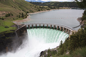
In comparison to water , capacitor is like a dam in the middle of our water flow, storing water for some time. In both cases, if no current/water flows into or out of the capacitor/dam, the water level/voltage remains constant. And the more current/water flows in or out, the faster the water level/voltage changes.
The unit for electrical capacitance is Farad. This corresponds to the volume of the lake. The higher the capacitance/volume, the more current/water the capacitor/dam can accept for each volt/meter rise.
.
4 - Base Audio Signals for Synthesis : Getting into the Sound
.
A-Sound and Signals
Sound is compression waves of changing air pressure over time, produced by some physical object moving back and forth (e.g. a speaker head).
Since a speaker's position is proportional to its input voltage, analog audio signals are usually represented as changing voltages over time.
Sometimes they are changing currents through a node at constant voltage, but changing voltages are much more common (e.g. this is what is present on a Line Out jack from a synthesizer).
Audio equipment is typically calibrated so that a variation of +/- 1 volt from ground (0V) is a loud sound for line level inputs/outputs; outputs that drive speakers can sometimes reach 50 volts or more (for several hundred watts sound systems).
.
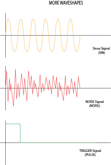
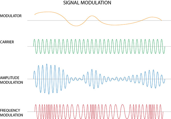
B-Base Wave Shapes
Let's have a look to some base audio waveshapes and how they look when changed in amplitude and in frequency.

That already gives us some good basics . Some more signals :
C-Signal Modulation
When you use a signal to modulate an other you have the following:
.
D-Audiovisual Example
Finally, here are some demos on the oscilloscope:
5 - Mixing and Filtering
Let's see the principle
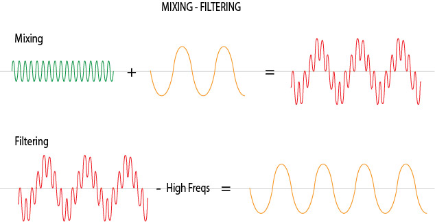
Basically by adding two different frequency signals it gives a signal more complicated and stronger, and by removing a portion of the signal frequencies we're getting something simpler but more accurate. An audio mixer provides complete these two functions simultaneously , for example.
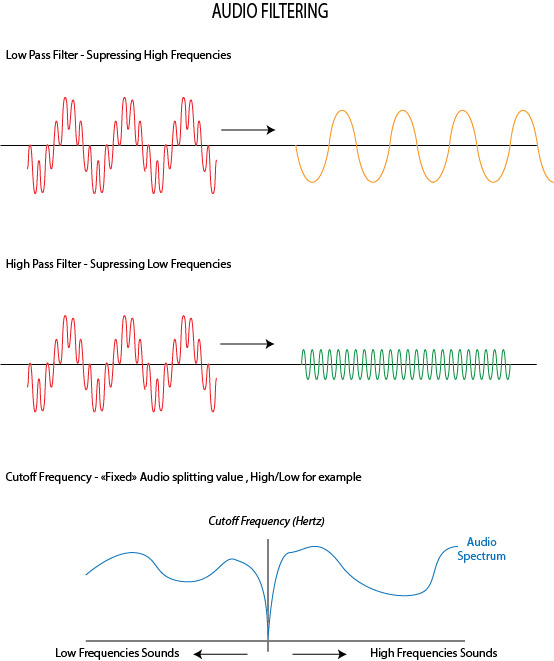
Audio filtering need some more precisions though :
.
6 - Analog / Digital, what's the difference?
As described above, analog audio is usually a changing voltage over time.
Digital audio is an array of (numeric) samples, each one corresponding to a particular amplitude/voltage at a particular time.
Therefore, when converted to digital form, audio has to be quantized (digitized, or divided into discrete elements) in both amplitude (voltage) and time. Here is the quantization in time:
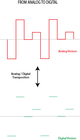
The frequency of the sampling (the little dots) is called the sample rate; common values are 44.1 kHz and 48 kHz. The higher the value, the better the accuracy of the digital representation.
The signal also has to be quantized in voltage/amplitude, because the computer has to represent each sample as a single number (with limited precision, often an integer (float for high precision) ).
GFX on Correction
If the numbers representing samples are integers, the quality of the quantization is called the bit depth.
Examples include 16-bit and 24-bit audio; these mean that each sample is represented by :
-16-bit integer = 2^16 = 65,536 possible levels
-24-bit integer = 2^24 = about 16 million levels
(8 bits depth = 2^8 = 0 to 254 levels and if we get signed -127 to +127 )
Often these values are represented as floating-point numbers within the computer, which gets rid of almost all the error (especially in modern DAWs that use 64-bit floating point).
The conversion to or from analog has to be done using an integer, and true 24-bit accuracy is almost impossible to get - and extremely expensive -. Most “24-bit” converters are actually effectively about 20-21 bits, due to noise and other factors.
.
7 - Resistor, Capacitor, Diode and Transistor
Back to Electricity !
There are some basic components used in electronics that need to be covered before going further.
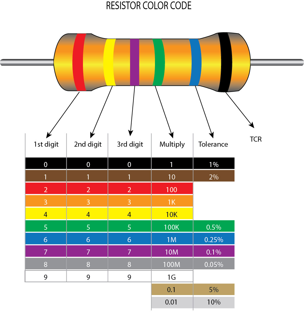
A-Resistor
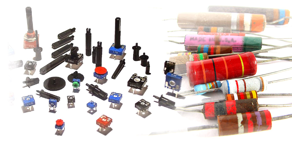
The resistor is a unpolarized passive component with a resisting value in ohms that acts in voltage regulation in circuitry. The color stripes on it describes it value, following a color code
Symbols
Here are the symbols for different types of resistors

- Fixed Value (with it simplification)
- Potentiometer/Variable Value (with it simplification)
- Rheostat (with it simplification)
- Photoresistor
- Thermistor
.
.
B-Capacitor
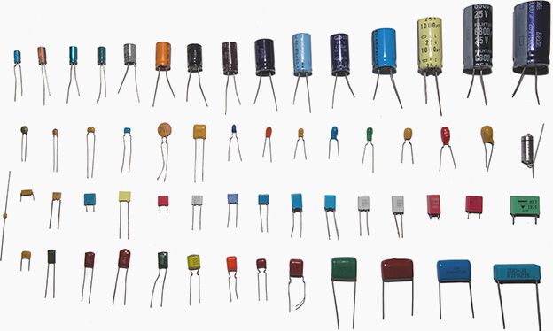
The capacitor is a passive component used to store electrical energy temporarily in an electric field with a value in farads . It is sometimes Polarized (Electrolytic , like the top line of capacitors in the picture above), sometimes not (Ceramic, like the 3 bottom lines of the picture above)
Symbols
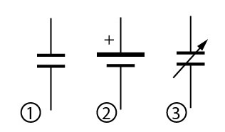
- Unpolarized Capacitor
- Polarized Capacitor
- Variable Capacitor
.
C-Diode
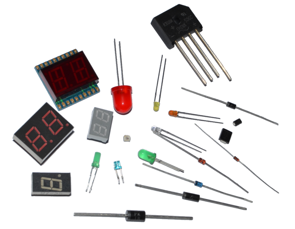
A diode is a polarized passive component that let pass the electrical flow in only one way . It acts like an anti-return system for electricity. By building a quad diode bridge you can make a voltage rectifier. It can also produce light (ex : LED)
Symbols
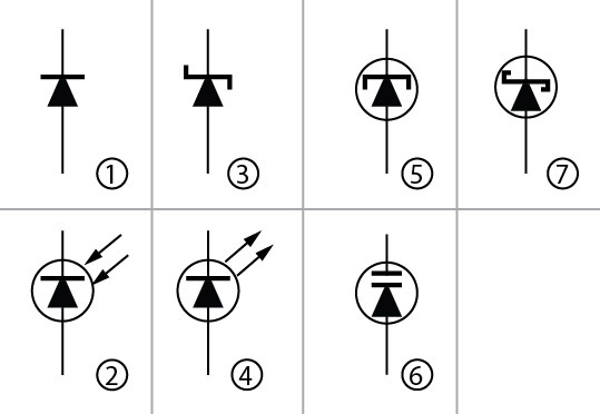
- Junction Diode , the most common diode with the LED
- PhotoDiode
- Zener Diode
- Light Emitting Diode or LED
- Tunnel Diode
- Varactor Diode
- Schottky Diode
.
D-Transistor
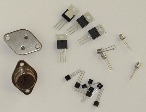
The Transistor is an active component that works as an amplifier or a driven switch. BJTs and FETs perform similar functions, but with a different type of input. Both kinds of transistors are devices that control the current flowing through them and can be used as digital switches or analog amplifiers.
In the digital case, the circuit around the transistor is designed so the input signal (current for a BJT or voltage for a FET) is large enough to turn on the transistor much more than the actual needed output current, or small enough to turn off the transistor completely.
In the analog case, the circuit is designed so that the transistor is operated in the region where small changes in input signal cause large changes in output current.
Symbols
Following the technology the transistor has been built, it has several symbols The current being controlled (i.e. the output current) is from top to bottom in all these pictures, i.e.:
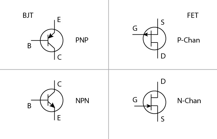
- from Emitter to Collector for PNP
- from Collector to Emitter for NPN
- from Source to Drain for P-channel FET
- from Drain to Source for N-channel FET
The third pin, Base or Gate, controls the amount of Current flow between the other two pins.
The difference between a BJT and a FET is that in a BJT, the output current is a function of the Current between Base and Emitter, and in a FET the output current is a function of the Voltage between Gate and Source.
.
8 - Kirchhoff's Circuit Laws
In electricity , as with water , the flows tend to regulate . The following relationships helps a lot about solving values in circuitry :
A-Current Law (KCL)
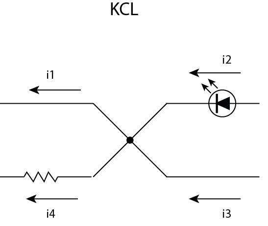
In other words , in a node , Current going to the node equals Current going from the node
i4 = i3 + i2 - i1
B-Voltage Law (KVL)

In other words, the voltage is balanced along the components rings ; ad = ab + bc + cd
V4 = V3+V2+V1
.
9 - Serial and Parallel Circuits
.
Current is the same for all of elements in a Serial circuit so : Total Current = Each component Current
Voltage is the same for all of elements in a Parallel circuit so : Total Voltage = Each component Voltage
.
A-Resistors Serial mounted
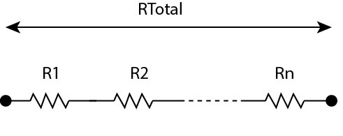
RTotal = R1 + R2 + … + Rn
.
B-Capacitors Serial mounted
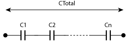
(1/CTotal) = (1/C1)+(1/C2)+… +(1/Cn)
.
C-Resistors Parallel mounted
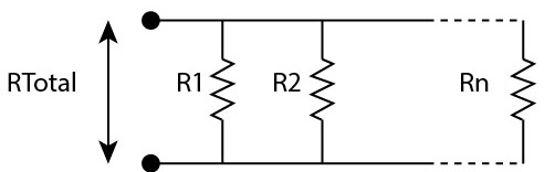
(1/RTotal) = (1/R1)+(1/R2)+… +(1/Rn)
.
D-Capacitors Parallel mounted
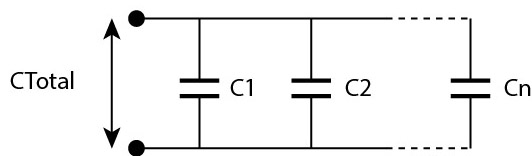
CTotal = C1 + C2 + … + Cn
.
10 - Operational Amplifier
An operational amplifier (aka OpAmp) is an electronic Integrated Circuit (IC) used in many purposes like amplifiers, mixers, filters and oscillators. Inside it looks like this (This is an example of OpAmp Design, not something General) :
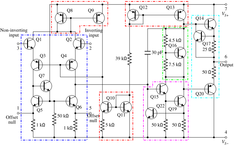
TL072/TL074/MCP6004 are some refs of Opamps used in MIDIbox Designs
It's represented in schematics by it's Symbol
A-Symbol
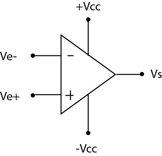
Vcc is the Bipolar power supply voltage for the operational amplifier . It is assumed it exists , but not always represented to make things clearer
B-Non inverted Amplifier
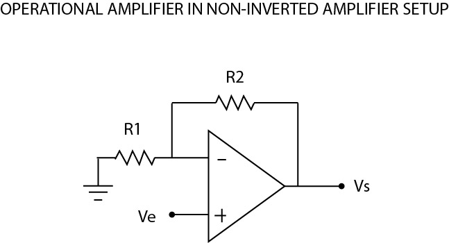
V- = Ve x ( R1 / ( R1+R2 ) )
Vs = Ve x ( 1 + ( R2/R1 ) )
Amplifying Gain = 1 + ( R2/R1 )
.
C-Schmitt Trigger aka Self Triggered Comparator
A Schmitt Trigger is an Operational Amplifier Setup “self-regulated”. Depending on the resistor values choosen, you have a fixed +/- Vtrigger.
Vs is kept maintained between -VTrigger and +Vtrigger.
The self-reaction is called a hysteresis loop . You can imagine a thermistance instead of R1 to have something wich regulates the power supply of a heater based upon its temperature.
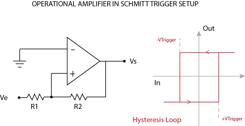
(+/-)VTrigger = (+/-)Vcc x ( R1/R2 )
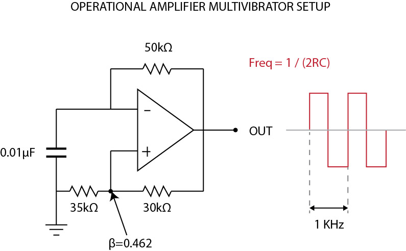
D-Basic Oscillator
Based upon a more complex setup, we can make an Oscillator :
.
E-Basic Mixers
These Circuits sums audio signals of multiple sources. There are passive and active mixers.
Let's see how it looks :

F-Basic Active First-Order Filters
As seen before , a filter sharpens a part of a complex signal. TODO : Talk about Order of filter and dB curve (1=3dB,4=24dB)
Here are some Basic First-Order filters based upon Operational Amplifier :
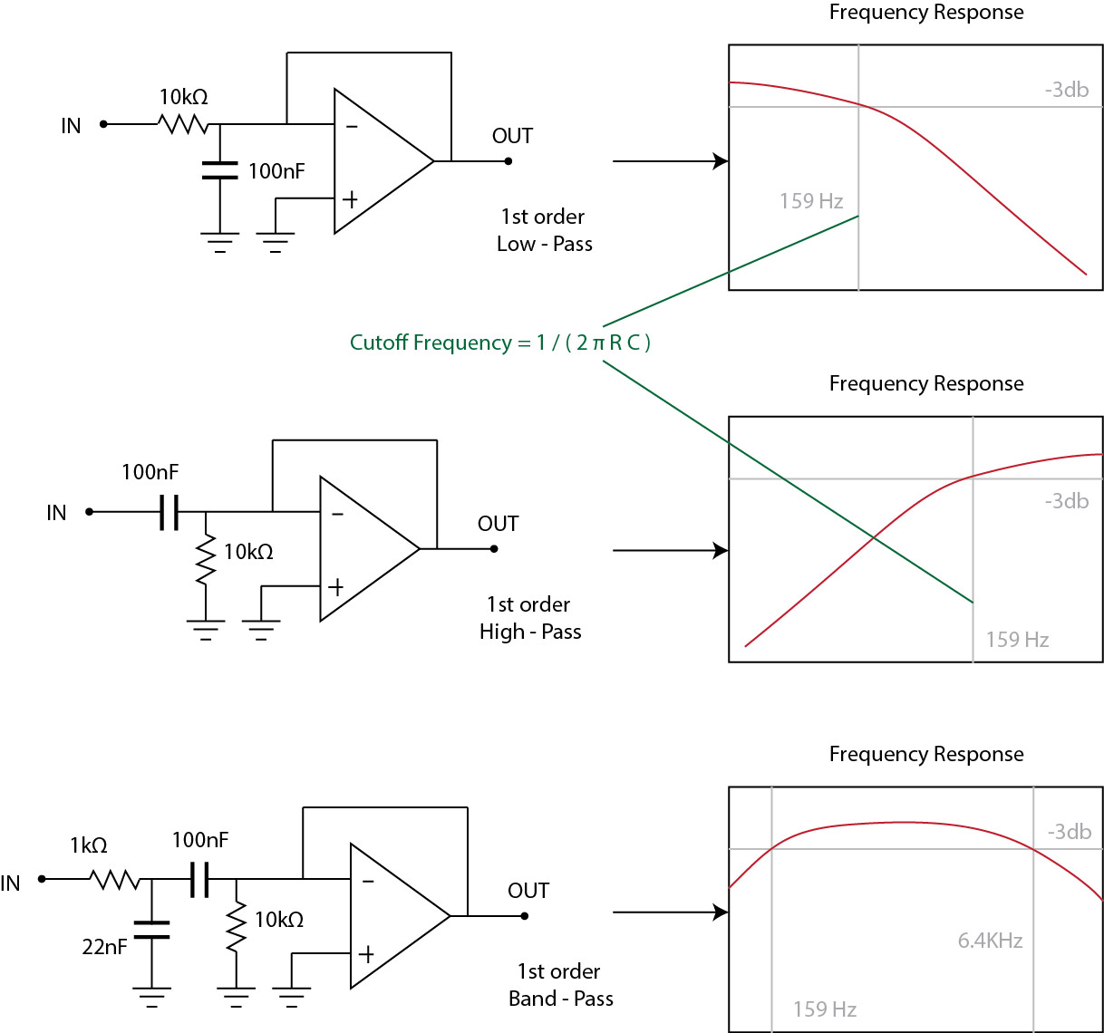
Low-Pass Filter
A low-pass filter let pass through frequencies below their cutoff frequencies, and progressively attenuates frequencies above the cutoff frequency. Low-pass filters can be used in audio crossovers to remove high-frequency content from signals .
High-Pass Filter
A high-pass filter does the opposite, passing high frequencies above the cutoff frequency, and progressively attenuating frequencies below the cutoff frequency. A high-pass filter can be used in an audio crossover to remove low-frequency content from a signal.
Band-Pass Filter
A bandpass filter passes frequencies between its two cutoff frequencies, while attenuating those outside the range. The contrary is a band-reject filter, wich attenuates frequencies between its two cutoff frequencies, while passing those outside the 'reject' range.A Band-pass filter can be used in an audio crossover to isolate medium-frequencies content from a signal.
Common Resistor/Capacitor Values for Cutoff Frequencies
 Add a basic table of usable Resistors/Capacitors values for some useful Cutoff Frequencies, with a base like that (in hertz) : 60 - 160 - 250 - 500 - 1000 - 2000 - 3500 - 5000 - 8000 - 10000 - 12000 - 15000
.
Add a basic table of usable Resistors/Capacitors values for some useful Cutoff Frequencies, with a base like that (in hertz) : 60 - 160 - 250 - 500 - 1000 - 2000 - 3500 - 5000 - 8000 - 10000 - 12000 - 15000
.