SEQv4+ ENC-PLATE
Eight encoders with switch functions connect to the SRIO chain on the le MEC board below. The PCB also holds Matias switches.
Note that two sets are required for a SEQv4+ build.
Schematic
The encoders are directly connected through the headers to DIN pins in the stacked PCB. The switches are connected to the matrix through diodes.
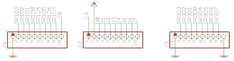
| Part | DIN SR | DIN pins/column | Cathode row |
|---|---|---|---|
| EN1 | 1 | 0,1 | – |
| EN2 | 1 | 2,3 | – |
| EN3 | 1 | 4,5 | – |
| EN4 | 1 | 6,7 | – |
| EN5 | 3 | 0,1 | – |
| EN6 | 3 | 2,3 | – |
| EN7 | 3 | 4,5 | – |
| EN8 | 3 | 6,7 | – |
| SW1 | 2 | D0 | C0 |
| SW2 | 2 | D1 | C0 |
| SW3 | 2 | D2 | C0 |
| SW4 | 2 | D3 | C0 |
| SW5 | 2 | D4 | C1 |
| SW6 | 2 | D5 | C1 |
| SW7 | 2 | D6 | C1 |
| SW8 | 2 | D7 | C1 |
BOM v1.0
Please find the current BOM on http://midiphy.com. The table below is depreciated and will not be updated.
| Type | Qty | Value | Package | Parts | Mouser | Reichelt | Conrad | Other | Notes |
|---|---|---|---|---|---|---|---|---|---|
| Diodes | |||||||||
| 8 | 1N4148 | THT | |||||||
| Encoders | |||||||||
| 8 | STEC12 | STEC12E08 | |||||||
| Headers | |||||||||
| 3 | 1*10 | through-board | MDF7-10S-2.54DSA(55) | ||||||
| Hardware | |||||||||
| 2 | M2 washer | 3mm? | |||||||
| 9 | M3 washer | 3mm? | |||||||
| 8 | knobs | TBD | |||||||
Note: two sets are required per SEQv4+!
Versions
v1.0: first release.
Assembly
Start with the eight encoders and diodes. Important to note:
- There is less than 3mm vertical distance between the stacked PCB sets. If diode or encoder legs are too long, they may short out the components below. I need to check the assembly. It might be that all parts on the ENC-PLATE PCB are soldered from the top and the legs protruding through are trimmed flush on the underside.
Once the diodes and encoders are okay, line up the headers, using a le MEC board and optionally some of the mounting points. Once you are happy, solder the three 1*10 male pin headers on the lower PCB, and only then fix the through-board female headers on the upper PCB.
- At this point, check again that there are no soldered joints bridging the two PCBs.
We need to first decide how the case will come together, but it is wise to now align the mounting washers. Lastly the Matias switches are mounted in the Plate PCB, and are soldered below.
- Keep in mind that once the switches are in, the only way to separate the two PCBs is to remove the switches!
So it could be that the DIN functions of buttons and encoders are tested prior to installing the switches.
License
Currently the design is © 2017 antilog devices with all rights reserved; all documentation is CC BY-NC-SA 3.0.