This is an old revision of the document!
Table of Contents
EASY CV
Test Equipment: CV-Destination MB33 MAM:
Introduction
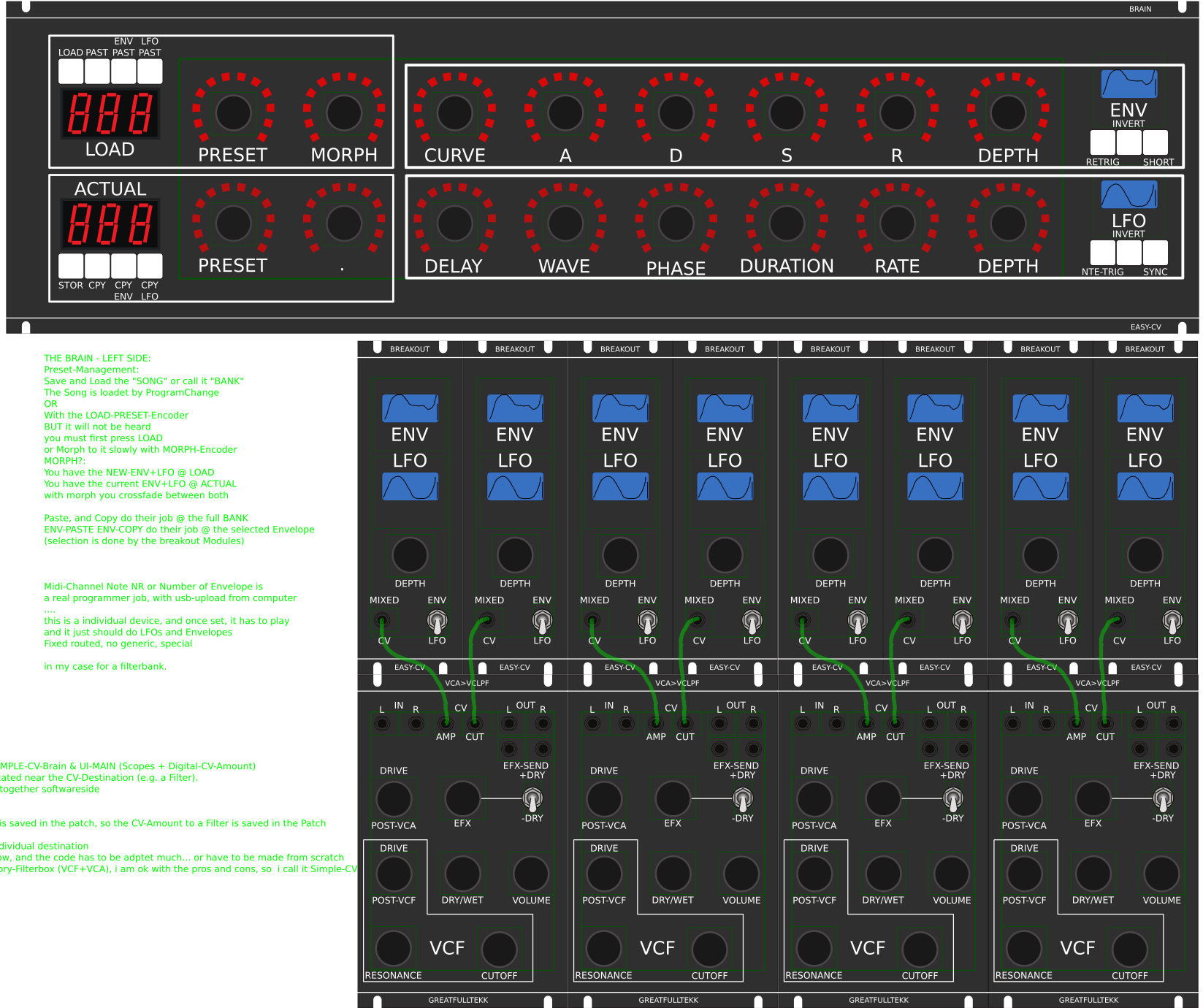
Digital created LFO+ENV with CV-Output. No Displays, No Menues, Minimal buttons, much Scopes, much Led-Ring-Rotarys (Planed for LRE-8x2CS), one big UI with complete functions for one LFO+ENV Voice… switching between the UI-Voices is done from the BREAKOUTMODULES…to this later
LFO+ENV are mixed together softwareside, to use only one CV-Output
8xCV-Outputs (VOICES) are supported > if u are on a VCF+VCA-Setup = 4 Voices on the Analog-Side (4xFilterbank)
Copy Paste for LFOs and ENVelopes between the Voices
Copy Paste for a Songa aka Preset aka Bank aka Program(change)
Jam Style Pattern load (next Preset Display) + Preset Morph between Current-Preset and Next-Preset
A Breakoutmodule for each CV-Output, with Depth-rotary, Focusswitch (Pushrotary), 2x Scopes (LFO+ENV) and LFO/ENV-Switch to show on one Display the Mixed Waveform & to switch the Rotary to “ENV” or “LFO” Mode (there is only space for one Encoder - maybe just make PAN Style, instead of 2 individual level -maybe more live feel?, how ever when using an 3Stage switch, i could disable MIX-View, or display it on ENV or LFO…maybe a good choise ;) ) The Depth-rotary has no Ledring, want to display it as a bar or as Value in the scope…
Whole thing will not be compatible on MB-CV concepts… i will copy code snippets and so on, but i have to understand it from scratch… anyhow this is not generic
FrontPanel
Brain
THE LEFT SIDE of the BRAIN > Preset-Management:
Save & Load the PROGRAM, can be done by Midi-ProgramChange -or With the LOAD-PRESET-Encoder
then press LOAD -or Morph to the next Program slowly with the MORPH-Encoder
-Another option is to take a PUSH-ENCODER for LOAD & STORE > and load and store it by pushing it… would free 2 buttons for other functions.
MORPH?:
-The Upper 7 Segment LED- Display: is the LOAD Display indicate the new Program with ENV+LFO
-The downer7 Segment LED- Dsipaly: is the STORE Display it indicates also the current Program with ENV+LFO
–with morph you crossfade between both Presets (be carefull, first Store the current Preset
Paste & Copy do their job @ the whole PROGRAM Memory
ENV-PASTE & ENV-COPY do their job @ the selected Envelope > (ENV-Voice selection is done by the breakout Modules) … LFO..same
Midi-Channel Note NR or Number of Envelope is a real programmer job (C), with usb-upload from computer
…. this is a individual device, and once set, it has to play > and it just should do LFOs and Envelopes
Fixed routed, no generic, special > in my case for a filterbank.
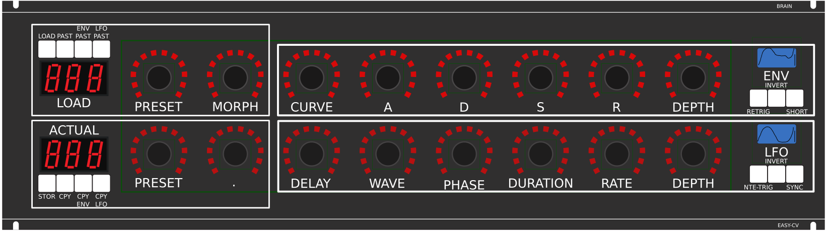 THE RIGHT SIDE of the BRAIN > LFO + ENV Settings (one Voice):
ADSR with:
THE RIGHT SIDE of the BRAIN > LFO + ENV Settings (one Voice):
ADSR with:
CURVE Paremter which give exponentially to it (no straight lines While Fall and Rise)
Short: just shorten the Maximal lenght of a Envelope, haveing more Feeling on Encoders
should change Scope Display also…
LFO: get synced with Midi, and there is a retrigger by Notes…
Phase: offsets the start-Phase
Delay: simple delay (nte-Trig)
Rate: clear from 8 wholes to 128th or so
Wave: access to the Waveforms
Duration: interpret Midisync in trippled, whole notes or whatever…
DEPTH: is the maximal Value of FALL and RISE and SUSTAIN, i know i loose resolution with this…but i have to have a memory filterbank,…doing depth instead with Potentiometers on Filtermodules… would give no memory…
BreakOut
1. Discharged UserInterface for the Brain in “Island mode” (Scopes + Digital-CV-Amount)
2. CV-Breakout EuroModule to be located near the CV-Destination (example: a Filter).
2 Waveforms (ENV+LFO) are mixed together softwareside
that bring 2 advanteges:
1.save one CV-Output
2. the Amplitude of each Waveform is saved in the patch, so the CV-Amount to a Filter is saved in the Patch
That bring 2 disadvanteges:
1.LFO or ENV cant get patched to individual destination
2.the Resulution gets lower 2 very low, and the code has to be adptet much… or have to be made from scratch
Because I use the device for a Memory-Filterbox (VCF+VCA), i am ok with the pros and cons, so i call it EASY-CV
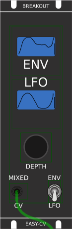 Envelope Scope: show the ENV-Waveform
or the Mixed-CV-Output-Waveform (when Switch is in LFO Mode)
and show the Envelope-Amount with a BAR or as numeric Value?
MIXED CV Plug: CV-Output > Mixed Waveform ENV+LFO
Switch @ ENV:
- Depth-Encoder change ENV Amount of the CV-MIX
- ENV Scope will show ENV Wave
- LFO Scope will Show CV-Mix
Switch @ LFO: visa versa ENV
Press the Encoders built in ENCODER-BUTTON:
will switch the BRAIN-A-D-S-R and L-F-O ENCODER to the Page for THIS Module…
workflow, see what you have with a Scope, over a filter, and edit exact this selected CV on the brain in full detail…
VCA-VCF
THE VCA and the VCF are controlled with each one CV - each CV has a LFO and a ENVELOPE digitaly mixed… fixed in routing.
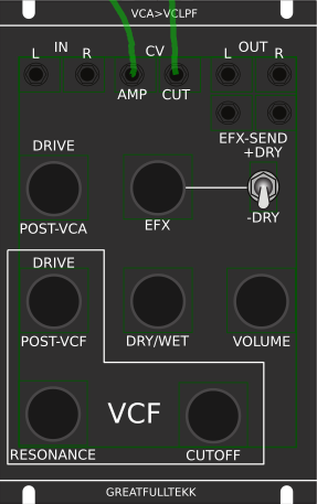 basicly a simple VCA (MS20Like) that drives the input of a Audio transformator 1:3 which is a Neutrik NTE10-3 (9€)
this “Tesla” Hi Gain - goes now thru the Post-VCA-Gain-Potentiometer - which then overdrives the 303 Filter (my prototype was a Freebase 383)
sound now goes to the Post-VCF-Gain-Potentiometer
now sound goes into a OP-Amp - to have the change for a light overdrive
From this point a EFX-Send Potentiometer send the Processed Signal to a extra Output (EFX-Send)
With the +DRY-Switch, we switch the orginal Signal additional to this EFX-Send-Potentiometer (or not)
Parallel to the EFX-Send Potentiometer is the DRY/WET Potentiometer it Pan between Orginal and Filtered Sound.
after DRY/WET come the Volume-knob and the Audio outs…
Original Schematics 303 - VCA-VCF
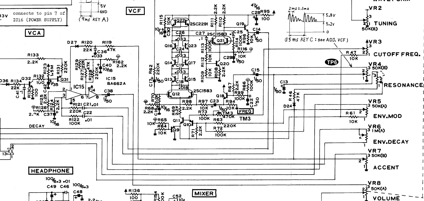
Mod Sources
 Fill with 303 mods
take orginal VCA (have a bunch of this ICS) or make MB33 Style with standart components…
Fill with 303 mods
take orginal VCA (have a bunch of this ICS) or make MB33 Style with standart components…
In order to not use those overprized MATCHED-PAIR-TRANSISTORS (over 2€ on the cheapest place) i have to use standart Transistors and make a VBE-MATCH on my own, i have already a PCB from here - to measure the transistors with a Multimeter: https://midisizer.com/other/vbe-matching/
Example for a Filterbank
Here are 8Envelopeś 4xfor VCF 4xfor VCA… in fact there could be used more then this for example 8xVCF and 8xVCA…since the BREAK-OUT-Modules are Modular, and they share the same “Main-UI”…the only limiting factor is the CODE…i am not a C-Guru, and maybe i will still have timing problems with 8x CV-Outs…we will see.
 I will use it to filter:
2xGuitar-Loopstations
1xGuitar
1xPercussion-Master
General Design
The panel size is 3U, Eurorack compliant
FrontPanel
PCBs
The Analog Circuits (VCF+VCA) get sandwitch as normal (not90° angeled)
Left-Part of the Brain on Breathboard:
7Segment: LTS547AP
Button: ShadowSE/ITT

3D View of Sandwitches
make concept
1. UI Parts Listing
BRAIN + BREAKOUT
| Value | Type | Qty |
|---|---|---|
| 3.5mm Jack | Vertical PCB-Mount | 13 |
| Switch | SPDT Vertical PCB-Mount ON-OFF-ON | 1 |
Fill Table
Pots / Knobs
- need special 4gang 50KB potentiometers for a STEREO Resonance (stereo filter, one UI)
- need special 4gang xxKB (50?) potis for a Stereo DRY/WET Mix
- need special 2gang xxKB (50?) potis for EFX Send Mix Stereo
- need special 2gang 50KA potis for CUT-OFF Stereo
- need special 2gang Post Transformator Potentiometer (Value have to look in my prototype which is used)
| Value | Type | Qty |
|---|---|---|
| 5K | Linear | x |
| 10K | Linear | x |
| 50K | Linear | x |
| 50K | Logarithmic | x |
| 100K | Linear | x |
| 1M | Linear | x |
| 2M? | Linear | x |
| Knobs | Soft/Plastic/Alu | x |
2. Analog Parts Listing
VCA-VCF-Board
Fill Table
3.Footprint Making in KiCAD
- ALPS Pots
- Alpha Pots
- 3,5mm Jack
- Switch
- Momentary Switch
- 7 Segment LED Display
- OLED DIsplay
- Rotary Encoder
have to be done
4. Schematics in KiCAD
have to be done
5.PCB Making In Kicad
PCB Making Order
- BRAIN PCBs:
a.Left-Brain
b.Right-Brain
- LRE8x2CS - is a generic PCB which i already have (fairlightiiś)
- BREAKOUT PCBs (maybe have to sandwitch because of shiftregisters and less space)
- FILTER PCBs (have to sandwitch)