This is an old revision of the document!
Table of Contents
Fadercore
Standard 220mm wide modules
VLR-8Enc
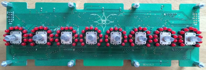
A PCB to add 8 Encoders with LED ring for each.
Eagle Files: https://github.com/novski/Midibox/tree/master/VLR-8Enc
BOM
BIll of Material
Allways look for the cheapest seller, the Price may vary heavy!!! And look for Local dealers preferred. http://www.midibox.org/dokuwiki/doku.php?id=where_to_order_components
The Encoders
I was fascinated about the RGB Shaft of this Encoder so i developed all opon this nice piece. Its not the cheapest but i sell them for a reasonable price.
And its still possible to use a non Illuminated Encoder.
The other Materials: Mouser
- 2x10pin Header, 517-30310-6002
- 2xULN2803, 595-ULN2803ADWR
- 9x100nF,594-K104K15X7RF53K2
- 6x10k, 774-77061103P
- 4×220, 652-4816P-T1LF-220
- 3×220, 660-MF1/2LCT52R221J
- 3x74HC165D, 771-HC165D652
- 3x74HC595D, 771-74HC595D
- 3xTPIC6B595, because the MOQ is 250 i deliver them for you with the PCB.
- 88xLED RED, 604-WP3A8HD
- 88xLED holder 6mm Height, 749-ELM-5-6MM
Project Order Basket on Mouser: http://www.mouser.com/ProjectManager/ProjectDetail.aspx?AccessID=a6dbae9ab7
The PCB is available under: http://vlrlab.com/lang/17-8enc.html
- 8 Encoder, 652-PEL12T4226FS1024 not on Projectlist because i deliver cheaper and with cap included..
The Encoder on VLRlabs.com https://www.vlrlab.com/encoder/13-bourns-rgb-led-encoder.html
How to get Started
If its your first SMD soldering you can follow this on t1:58 : http://www.youtube.com/watch?v=5uiroWBkdFY I recommend to not buy solder paste, instead buy some flux-paste like this on Mouser: 590-8341-10ML
Prepare the PCB
Start with the SMD parts and then go on the the conventional parts also on the Bottom side. Don't forget the R11,12,13. Then go on with the Topside and the LEDs before soldering the Encoder as last. Check the Connections with a Lens.
Prepare the Connection
Connect the core on J8/9 to J1 of the VLR-8Enc board.
Test it in MIOS
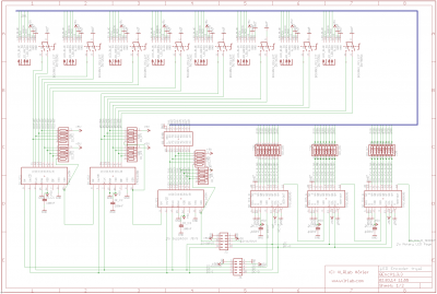
To make it work with MIOS .NGC File we need to know how the shift-registers are connected.
Inputs:
1# Encoder 1-4
2# Encoder 5-8
3# Encoder Button 1-8
Outputs:
1# RED Shaft LED 1-8
2# GREEN shaft LED 1-8
3# BLUE shaft LED 1-8
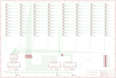
4# LED Ring Row 1-8
5# LED Ring Selct 1-8
6# LED Ring Select 9-11
Assuming that the VLR-8Enc is the first device on the chain of J8/9 we need to configure it like this:


