This is an old revision of the document!
Table of Contents
Midibox LCD Module
An LCD module isn't an MBHP module, you buy the LCD screen with the PCB attached and driver chips on-board, and that is your LCD module. Here you can find information how to use an LCD with the Midibox MBHP Core module.
See also: Troubleshooting LCD Displays
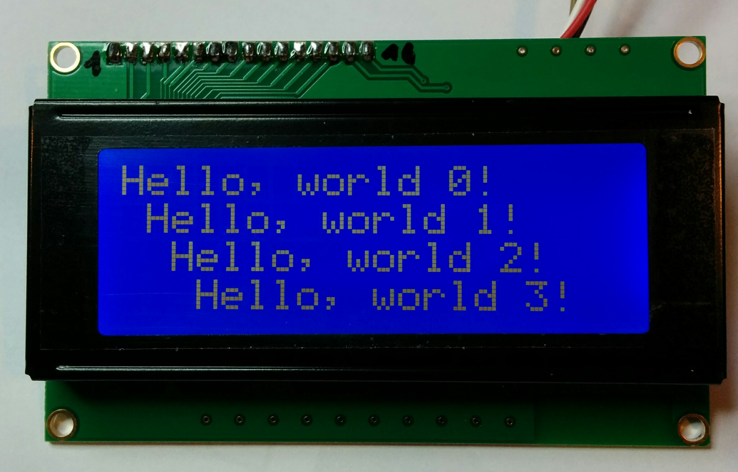
This is a 4×20 CLCD
LCD Technology
LCD is an acronym for Liquid Crystal Display. It's a particular form of video technology in portable devices, clocks, watches, and computing devices.
LCD displays utilize two sheets of polarizing material with a liquid crystal solution between them. An electric current passed through the liquid causes the crystals to align so that light cannot pass through them. Each crystal, therefore, is like a shutter, either allowing light to pass through or blocking the light. In clocks and counters that use LCDs, the pattern often emulates LEDs, though LCDs are NOT diodes.
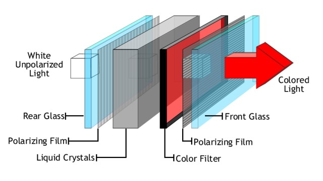
Monochrome LCD images usually appear as blue or dark gray images on top of a grayish-white background. Color LCD displays use two basic techniques for producing color, passive matrix is the less expensive of the two technologies.
The other technology, called thin film transistor (TFT) or active matrix, produces color images that are as sharp as traditional CRT displays. Recent passive matrix displays using new CSTN and DSTN technologies produce sharp colors rivaling active matrix displays. Most LCD screens used in notebook computers are backlit to make them easier to read.
Typical Core32 Connection
Character LCD (CLCD) MIDIbox Compatibility List
MIOS supports internally Hitachi HD44780 compatible character displays. They are the industry standard for the character displays, but not all “standard” displays have this particular chip.You can use a larger LCD, like 2×20 or 4×20, and the standard Midibox projects will just use the 2×16 characters in the top left corner. Many, however, have compatible chips which will work just as well.
Here is a list of compatible CLCD Controllers: Have a look to the datasheet of the display you want to plug, you will get this info. If your LCD has one of these chips, there are good changes to get it work.
These chips have similar instruction set, data bus and timings are like original HD44780 (or faster, which shouldn't matter). But this only means controller chip is compatible with the driver designed for HD44780.
It may not be exactly what you need, forexample it may require a negative backlight voltage, which is independent of the driver IC. It's strongly recommended to get a display, that has a datasheet available.:
- Hitachi HD44780
- Epson SED1278
- NJR NJU6408B
- NJR NJU6468
- NJR NJU6470
- Novatek NT3881D
- OKI MSM6222
- Samsung KS0066
- Samsung KS0076(b)
- Samsung KS0070
- Samsung S6A0069
- Sanyo LC7985NA
- Sunplus SPLC780
Possibly:
- UM3881B UMC - I haven't found any reports about this chip
- Toshiba T7934 - Instruction set compatible, has extra characters in CG ROM, it shouldn't matter
- Sitronix ST7036 - Instruction set compatible, although it should, did not work for me
Graphical LCDs (GLCD) MIDIbox Compatibility List
Contribute !
Report your experiments / code you've been writing for CLCD to the forum and here if you have a wiki account
Where to buy ?
Have a look Here
LCD Connection
Connectivity
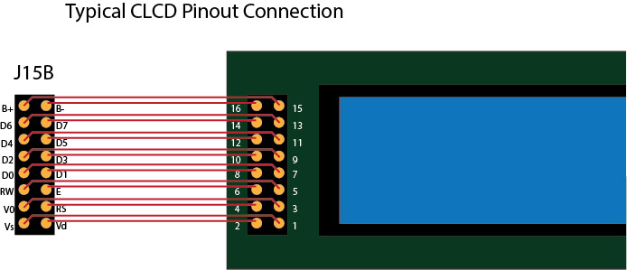
The pin assignments of the LCD interface J15 unfortunately aren't straightforward because they were chosen to ease construction of the Core. So, you have to take special care for the interconnections. Pin assignments on the LCD modules also vary. Be sure you get a data sheet with the pinout for your LCD module.
There is an LCD interconnection test available at the MIOS Download section which allows you to toggle each individual data/control pin with a Modulation Wheel of a MIDI keyboard, or with the appr. CC Events - e.g. from MIDI-Ox or MIOS Studio. It's a very useful test to ensure, that all wires are connected, that they are in the right order, and that there are no short circuits between the pins.
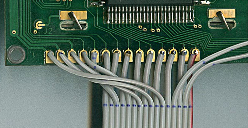
Jim Henry wrote a superb guide about LCD soldering which is not only interesting for beginners - thanks Jim!
- The soldered connections to the LCD are somewhat fragile. The one pictured in my guide broke after a few weeks of use. (I just have all the boards loose as I try different configurations so I am hard on the connections.) I suggest folding the ribbon cable back onto itself about 1/2“ from the soldered connections and securing the ribbon cable to the LCD's PCB to provide some mechanical support for the soldered points. I just taped the ribbon cable to the opposite edge of the PCB. I'll update the guide once I get some hours accumulated on this additional step to verify that it protects the soldered connections. Jim Henry
- So long as the operating system (MIOS) hasn't been uploaded via MIDI, but the bootloader has been burned to the chip, the LCD won't be fully initialized, and will show black bars at the upper line. If you don't see these bars, adjust the contrast pot. The highest contrast can be achieved with V0=0V (you can adjust this voltage with the trimpot P2).
- If you've connected a second LCD, it won't function until an application which supports this option (i.e. MIDIbox SEQ, MIDIbox LC) has been uploaded.
Programming LCDs : MIOS LCD Offsets
Some words by TK in response to this question:
The display offsets are handled by MIOS in a way which allows to use the same cursor positions on any kind of LCD. With MIOS_LCD_YAddressSet the LCD specific cursor offsets are mapped to the MIOS specific cursor offsets.
64 characters (0x40) are reserved for each line, up to 4 lines are (natively) supported:
- 1st line begins at 0x00
- 2nd line begins at 0x40
- 3rd line begins at 0x80
- 4th line begins at 0xc0
And these lines have to be mapped to the real address offsets of your LCD - this can normaly be found in the datasheet, the most common cases are documented in the functional description of MIOS_LCD_YAddressSet: http://www.ucapps.de/mios_fun.html#MIOS_LCD_YAddressSet
For a 2×40 following settings are working:
- Y0: 0x00
- Y1: 0x40
- Y2: doesn't matter (*)
- Y3: doesn't matter (*)
(*) note: if a value between 0x80…0xff is specified here, it is assumed that the 3rd and 4th line is mapped to a second LCD
Centering the screen just means to add additional offsets to these addresses, e.g. let's say you've a 2×40 display, but only 16 columns are used, this means that you need to add 12 to each offset:
- Y0: 0x00 + (40-16)/2
- Y1: 0x40 + (40-16)/2
- Y2: doesn't matter (*)
- Y3: doesn't matter (*)
Thats how MIOS supports LCDs.
Additional hints:
So long as the operating system (MIOS) hasn't been uploaded via MIDI, the LCD won't be initialized and shows black bars at the upper line. If you don't see these bars, adjust the contrast pot. The highest contrast can be achieved with V0=0V (you can adjust this voltage with the trimpot P2).
A message should appear on screen once MIOS is up and running.
Note: if you've connected a second LCD, it won't function until an application which supports this option (i.e. MIDIbox SEQ, MIDIbox LC) has been uploaded.
More Information
- http://compiler.kaustic.net/glcd/ GLCD char maker made by Captain Hastings