This is an old revision of the document!
Table of Contents
MB-606RE
Introduction
The MB-606RE is a re-edit of CYM/HH and BD/SD drum parts of the Roland TR-606 to be controlled via MIDI (midibox) or CV through analog-Sequencers , in a a Eurorack-designed panel.
Well known Circuit Mods from around Web & time are included by default.
FrontPanel

General Design
The MB-606re is part of the EuroLand Group… (606, 808, 909)
It can be used in 2 Cases:
Midi /CV+Trig
1. Midi: Use the MB-Modulbox Standartmodules, for Digital UI and CV+Trig-Generation
2. CV+Trig: Just Plug CV or Trig Jacks into the Analog Modules…without Midibox.
Use with Midi
MB-Modulbox Main PCB UI
Access to System-Settings, Channel, NoteNumbers
CV+Trig Out-Jacks for Euroland Drum Modules
MB-Modulbox 8xPotentiometer Module
When using the Euroland Modules via Midi, then there are some Performance Parameters aviable:
All Functions have effect on all 8 Voices @ once.
1.Velocity Offset (-+64 > with Center Postiton = normal)
2.Velocity Kill depending Note Kill (-+64 > with Center Position = normal > Full Spectrum)
3.Random Kill (0=full Kill, 127 no Kill, Normal Position > 127)
4.Velocity 2 TriggerLength (-+64 > with Center Position = normal 10ms, turn right:time inc by velocity in%, turn left:decrease%)
5.Accent: (0-127-normal 127)
6.——: could be something like Roll
7.——: not used, could be something like a Accent for a Group of CVs
8.——: not used, could be something like a Accent for a Group of CVs
accessable via MB-Modulbox 8xPot - PCB. Just plug it in, and acitivate the AIN-Port in MIOS
MB-Modulbox 8x8 LED-Button-Matrix
Set CV + Trig Routing (some kind of trigger matrix), standard is 1:1 routing, so no need for this if you use a fixed setup.
Use with Midi or with Analog CV+Trig
Here are only the Analog-Drum-PCB discussed, since all other Digital UI is based on MB-Modulbox Standart Modules, the MB-Modulbox Main PCB2 is special Variant, described here.
606 BD+SD, 606 HH+CY
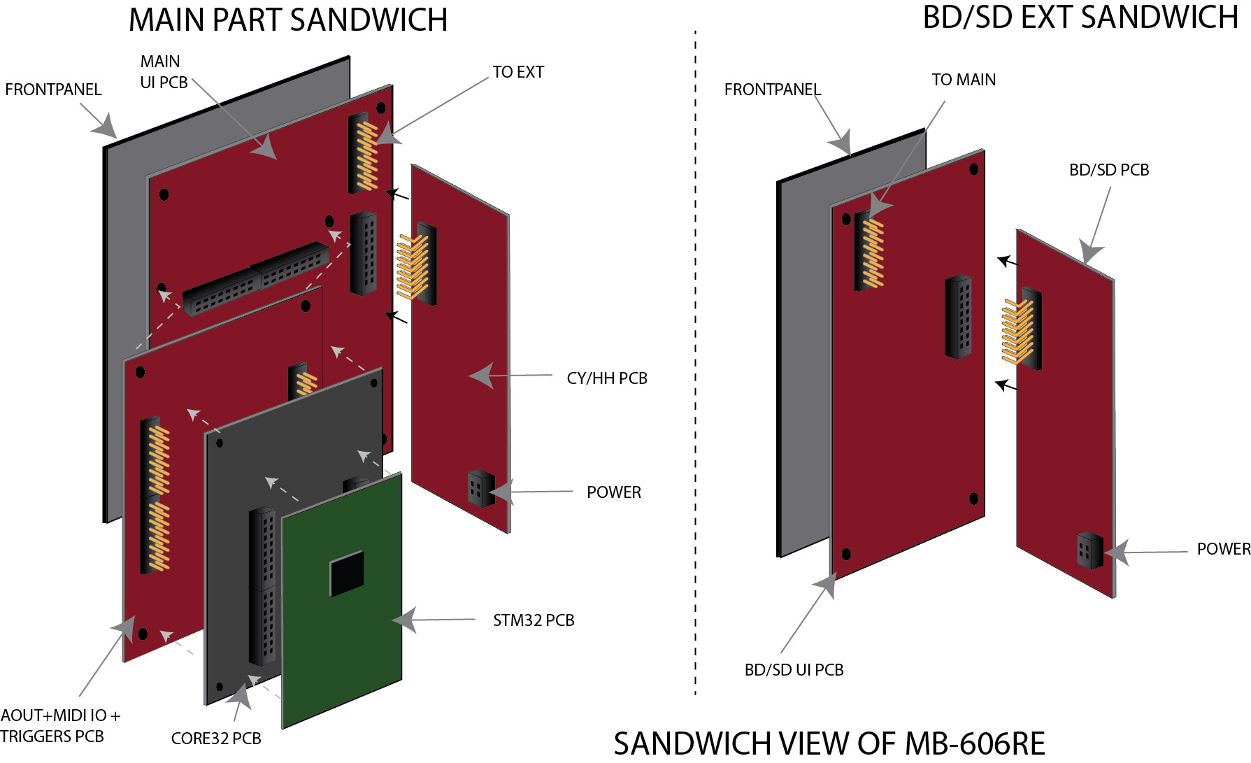
To spare Space: we sandwich in 2 layers
- 1st PCB : BD+SD UI-PCB / HH+CY UI-PCB »> Breakoutboard+Potentiometer Boards
- 2nd PCB : Analog Circuits: 2n We get the Analog Circuits mounted 90° angled with vertical female socket and angled DIL Pinheaders for better heat dissipation
Sandwich view - Analog Boards
.
Original Schematics
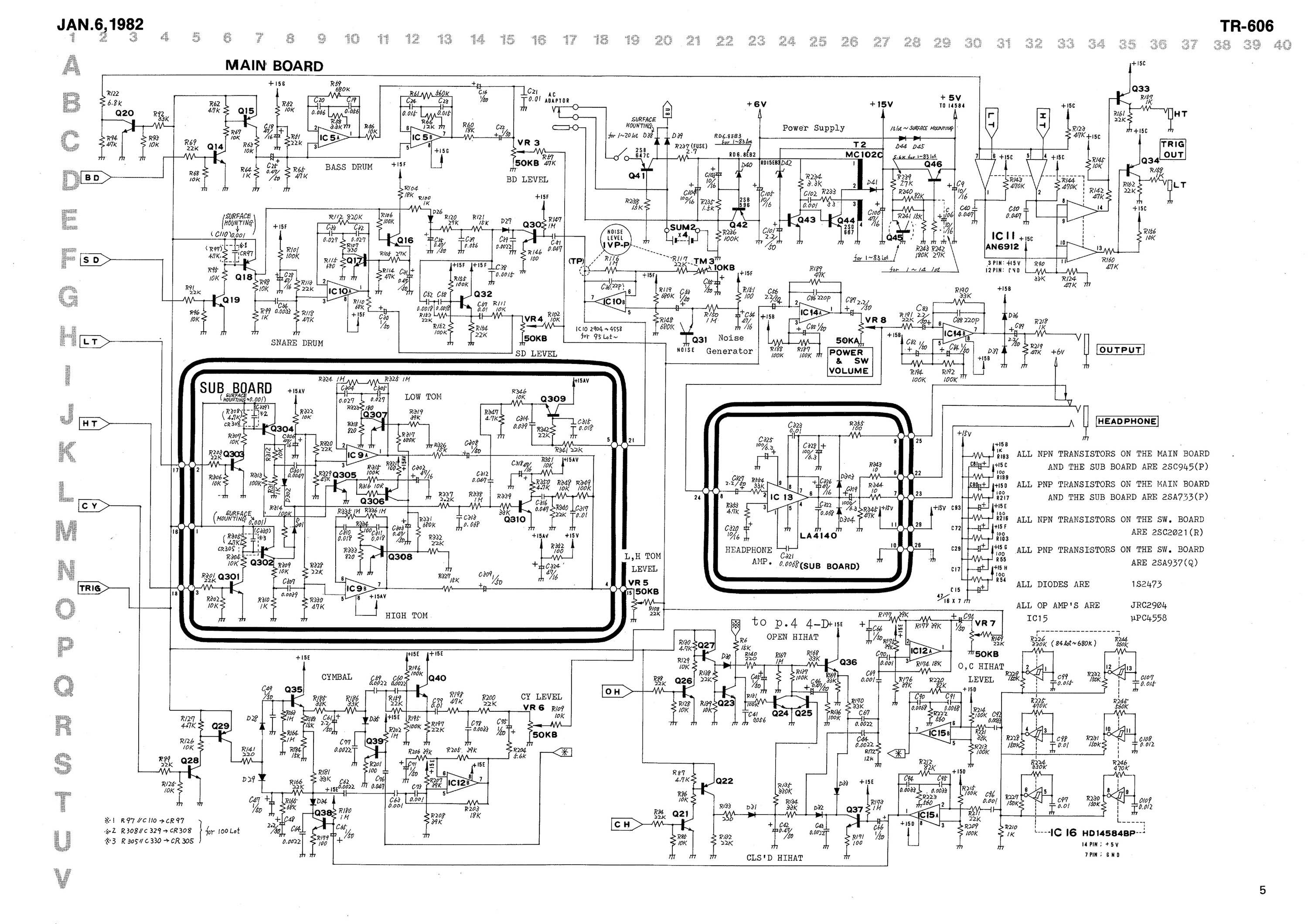
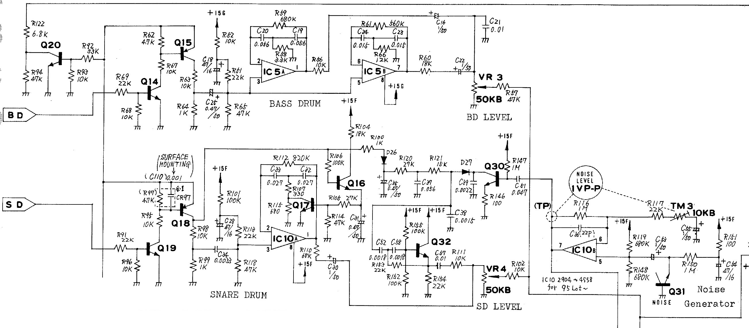
BD / SD
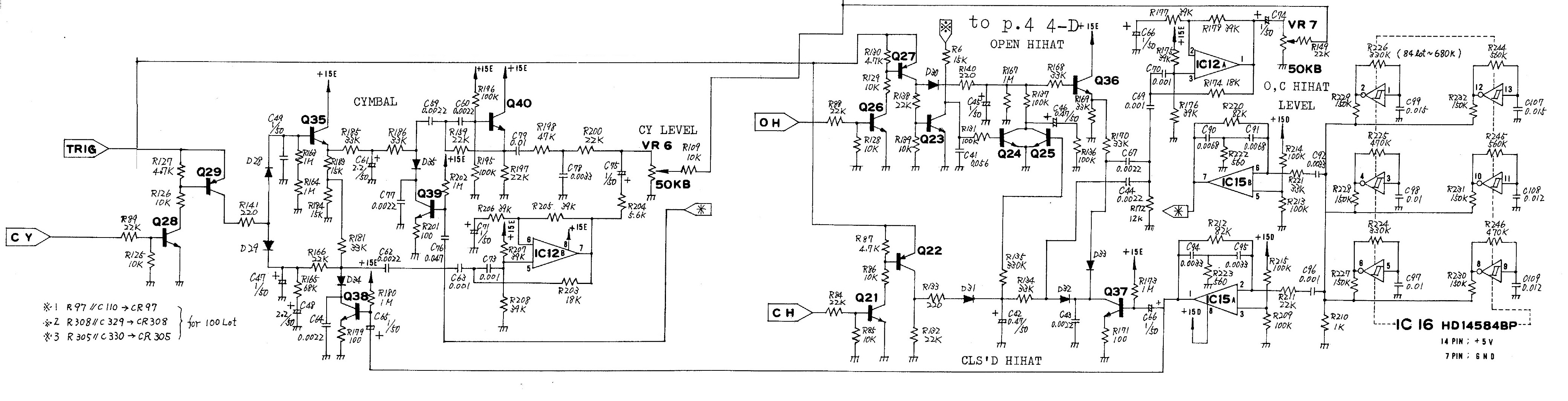
CY / HH
Mods
Mod Sources
Analog Mods
- HH Noise: 10K or 50K lin or log,have to check , orginally 10K trimpot, only change volume not to absolutely silence.
- 6OSC-Gain: 50K log (not sure)
- CY-HH Ext: 50K lin
- CY-HH BPF-Resonance: 100K Stereo lin
- CY-HH BPF1: 5K lin
- CY-HH BPF2: 5K lin
- CY-HPF: : 50K log
- HH-HPF:50K log
- OH Decay: 1M lin
- CH Decay: 1M lin
- CY Decay: 2M lin (internet) Phats machine has a 4M log
- BD Tune: 50K Log
- BD Decay: 2M lin
- BD Tone: 100K lin
- Noise: 50K log
- SD Snappy: 100K lin
- SD Decay: 500K lin
- SD Tune: 1M lin
On-Going
1. UI Parts Listing
Frontpanel
| Value | Type | Qty |
|---|---|---|
| 3.5mm Jack | Vertical PCB-Mount | 13 |
| Switch | SPDT Vertical PCB-Mount ON-OFF-ON | 1 |
Pots / Knobs
| Value | Type | Qty |
|---|---|---|
| 5K | Linear | 2 |
| 10K | Linear | 6 |
| 50K | Linear | 6 |
| 50K | Logarithmic | 6 |
| 100K | Linear | 2 |
| 1M | Linear | 3 |
| 2M? | Linear | 2 |
| Knobs | Soft/Plastic/Alu | 31 |
2. BD/SD - CYM/HH Parts Listing
Modded BD
| Value | Type | Qty | Original Designation |
|---|---|---|---|
| 2SA733/BC547 | Transistor | 1 | Q15 |
| 2SC945/BC557 | Transistor | 2 | Q14,Q20 |
| JRC2904/LM2904 | OpAmp | 1 | IC5 |
| 50KΩ | Pot Log | 2 | Level, ModTune |
| 100KΩ | Pot Linear | 1 | ModTone |
| 2MΩ | Pot Linear | 1 | ModDecay |
| 0,47µF/50V | Capa Elec | 1 | C25 |
| 1µF/50V | Capa Elec | 1 | C22 |
| 33µF/16V | Capa Elec | 1 | C19 |
| 47µF/16V | Capa Elec | 1 | C18 |
| 0,015µF | Capa Ceram | 2 | C23,C24 |
| 0,01µF | Capa Ceram | 1 | C21 |
| 1KΩ | Res 1/4W | 1 | R64 |
| 3,3KΩ | Res 1/4W | 1 | R58 |
| 4,7KΩ | Res 1/4W | 1 | R62 |
| 6,8KΩ | Res 1/4W | 1 | R122 |
| 10KΩ | Res 1/4W | 5 | R52,R56Mod/R67/R68/R93 |
| 22KΩ | Res 1/4W | 2 | R51,R69 |
| 33KΩ | Res 1/4W | 1 | R92 |
| 47KΩ | Res 1/4W | 3 | R59,R65,R94 |
| 100KΩ | Res 1/4W | 1 | R57 |
| 470KΩ | Res 1/4W | 1 | R56 |
| 560KΩ | Res 1/4W | 1 | R61 |
Modded Noise/SD
| Value | Type | Qty | Original Designation |
|---|---|---|---|
| 2SA733/BC547 | Transistor | 1 | Q18 |
| 2SC945/BC557 | Transistor | 6 | Q19,Q17,Q16,Q30,Q31,Q32 |
| JRC4558/NJM4558D | OpAmp | 1 | IC10 |
| 50KΩ | Pot Log | 2 | Level,Noise |
| 100KΩ | Pot Linear | 1 | ModSnappy |
| 500KΩ | Pot Linear | 1 | ModDecay |
| 1MΩ | Pot Linear | 1 | ModTune |
| 1N4148 | Diode | 2 | D26,D27 |
| 22pF | Capa Ceram | 1 | C36Mod |
| 0,001µF | Capa Ceram | 1 | C97 |
| 0,0015µF | Capa Ceram | 1 | C38 |
| 0,0018µF | Capa Ceram | 2 | C52,C58 |
| 0,0033µF | Capa Ceram | 1 | C34 |
| 0,01µF | Capa Ceram | 1 | C57 |
| 0,027µF | Capa Ceram | 2 | C32,C33 |
| 0,047µF | Capa Ceram | 1 | C51 |
| 0,055µF | Capa Ceram | 1 | C37 |
| 2,2µF | Capa Ceram | 1 | C35Mod |
| 0,47µF/50V | Capa Elec | 2 | C31,C35 |
| 1µF/50V | Capa Elec | 2 | C30,C53 |
| 47µF/16V | Capa Elec | 2 | C28,C54 |
| 100Ω | Res 1/4W | 2 | R146,R151 |
| 330Ω | Res 1/4W | 2 | R107,R153 |
| 680Ω | Res 1/4W | 1 | R115 |
| 1KΩ | Res 1/4W | 2 | R99,R100 |
| 2,2KΩ | Res 1/4W | 1 | R91Mod |
| 4,7KΩ | Res 1/4W | 1 | R97 |
| 5,6KΩ | Res 1/4W | 1 | RDecayMod |
| 10KΩ | Res 1/4W | 5 | R95,R96,R98,R102,R111 |
| 15KΩ | Res 1/4W | 1 | R121 |
| 18KΩ | Res 1/4W | 1 | R104 |
| 22KΩ | Res 1/4W | 2 | R113,R154 |
| 27KΩ | Res 1/4W | 2 | R105,R120 |
| 47KΩ | Res 1/4W | 2 | R114,R118 |
| 68KΩ | Res 1/4W | 2 | R110,R148 |
| 100KΩ | Res 1/4W | 4 | R101,R106,R152,R155 |
| 470KΩ | Res 1/4W | 1 | R112Mod |
| 680KΩ | Res 1/4W | 1 | R119 |
| 1MΩ | Res 1/4W | 3 | R116,R147,R150 |
Modded CY
| Value | Type | Qty | Original Designation |
|---|---|---|---|
Modded HH
| Value | Type | Qty | Original Designation |
|---|---|---|---|
3.MB-Modulbox-Main2-PCB > 4xAOUT_LC + 8xTrigger In PCB Parts Listing
Integrate CV Scaling circuit
| Value | Type | Qty | Original Designation |
|---|---|---|---|
4.Footprints List
- ALPS Pots
- Alpha Pots
- 3,5mm Jack
- Switch
5. Schematics in KiCAD
KiCad Pre-Project MAIN by Phatline » shematics have to be overworked
- Analog drums PCBs
- UI PCBs
- Special MB-Modulbox-Main2 PCB (4xAOUT-LC+8xTrigger out)