This is an old revision of the document!
SEQv4+ ENC-PLATE
Eight encoders with switch functions connect to the SRIO chain on the le MEC board below. The PCB also holds Matias switches.
Note that two sets are required for a SEQv4+ build.
Schematic
The encoders are directly connected through the headers to DIN pins in the stacked PCB. The switches are connected to the matrix through diodes.
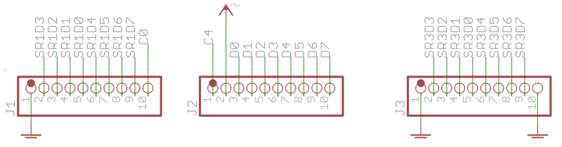
| Part | DIN SR | DIN pins/column | Cathode row |
|---|---|---|---|
| EN1 | 1 | 0,1 | – |
| EN2 | 1 | 2,3 | – |
| EN3 | 1 | 4,5 | – |
| EN4 | 1 | 6,7 | – |
| EN5 | 3 | 0,1 | – |
| EN6 | 3 | 2,3 | – |
| EN7 | 3 | 4,5 | – |
| EN8 | 3 | 6,7 | – |
| SW1 | 2 | D0 | C0 |
| SW2 | 2 | D1 | C0 |
| SW3 | 2 | D2 | C0 |
| SW4 | 2 | D3 | C0 |
| SW5 | 2 | D4 | C1 |
| SW6 | 2 | D5 | C1 |
| SW7 | 2 | D6 | C1 |
| SW8 | 2 | D7 | C1 |
BOM
Note: two sets are required per SEQv4+!
| Type | Qty | Value | Package | Parts | Mouser | Reichelt | Conrad | Other | Notes |
|---|---|---|---|---|---|---|---|---|---|
| Diodes | |||||||||
| 8 | 1N4148 | THT | |||||||
| Encoders | |||||||||
| 8 | STEC12 | STEC12E08 | |||||||
| Headers | |||||||||
| 3 | 1*10 | through-board | MDF7-10S-2.54DSA(55) | ||||||
| Hardware | |||||||||
| 2 | M2 washer | 3mm? | |||||||
| 9 | M3 washer | 3mm? | |||||||
| 8 | knobs | TBD | |||||||
Versions
v1.0: first release.
Assembly
Start with the SMT parts (caps, ICs and RN), then the resistors and diodes with correct polarity. Headers, switches (read below first!), encoder, caps and knobs.
Important: insert the LEDs into the switches before soldering them! It's quite hard to bend the legs once the switches are in place. The LED legs should not interfere with the switch action; i.e. the button should be pressed and released without getting caught on the legs.
Ensure that when the switch is soldered in, the LED is correctly polarised. Round part (anode) of the LED to the circled pin; flat part (cathode) to the line:

License
Currently the design is © 2017 antilog devices with all rights reserved; all documentation is CC BY-NC-SA 3.0.