This is an old revision of the document!
Table of Contents
SEQv4+ le MEC
This board holds the SEQ's illuminated buttons, which are driven from a shift register matrix. The ENC-PLATE board stacks on top.
Schematic
A shift register chain of 3 DIN 74HC165 and 2 DOUT 74HC595 chips are used. Two of the DINs scan the encoders and one scans the button columns. The DOUT parts are connected into a matrix. Note that both the high and low sides have driver transistors (PNP and NPN, respectively). This means that the anode side of the matrix will operate with inverted behaviour (pin high = LED off).
There are special instructions for connecting the parts which are covered below.
BOM v1.0
| Type | Qty | Value | Package | Parts | Mouser | Reichelt | Conrad | Other | Notes |
|---|---|---|---|---|---|---|---|---|---|
| Resistors | |||||||||
| 1 | wire link | THT | R17 | ||||||
| 18 | 47R 5% | THT | RJ1-9 | see instructions | |||||
| 8 | 100-220R 5% | THT or 1206 | SJ1-8 | see instructions | |||||
| 16 | 1k 5% | THT | R1-16 | ||||||
| Resistor networks | |||||||||
| 3 | 9*10k | SIP10 | RN1-3 | bussed, not 5 pairs of resistors | |||||
| Capacitors | |||||||||
| 5 | 100n | 1206 | C1-5 | ||||||
| 0 | do not fit | C6 | |||||||
| Diodes | |||||||||
| 24 | 1N4148 | THT | |||||||
| LEDs | |||||||||
| 16 | RGB flat | superflux | ELV: 68-10 94 64 | see instructions | |||||
| 8 | various | 3mm | insert into switches | ||||||
| Transistors | |||||||||
| 8 | BC808 | PNP SO-23 | |||||||
| 8 | BC818 | NPN SO-23 | |||||||
| ICs | |||||||||
| 3 | 74HC165 | SOIC16 | IC1, IC3, IC5 | 595-SN74HC165DR | |||||
| 2 | 74HC595 | SOIC16 | IC2, IC4 | ||||||
| Switches | |||||||||
| 16 | Matias | QuietClick | SW1-16 | see notes | |||||
| 8 | MEC/APEM | 3FTH9 | SW17-24 | 642-3FTH9 | TASTER 3FTH9 | 705276 - 62 | |||
| Headers | |||||||||
| 1 (3) | 1*3 | male | |||||||
| 3 | 1*10 | male | |||||||
| 2 | 2*5 | male | |||||||
| Hardware | |||||||||
| 16 | switchcaps | ALPS-DSA clear | |||||||
| 8 | switchcaps | 22.5mm | 642-1S11-19.0 | 1S11-19.0 | |||||
note that two sets are required per SEQv4+ build!
Versions
v1.0: first release.
Assembly
Take your time as some of these parts require some patience.
LEDs
High-brightness LEDs are often expensive or don't have viable mounting options. To get around this, we will use flat-top superflux/piranha RGB LEDs and bend the legs over to make a pseudo SMT part :). There are at least two different LED pinouts, so make sure you know how yours function.
Important is:
- Flat top (or maybe a filed-down dome)
- RGB LEDs with a common cathode
- With the LED standing on its legs, viewed straight on, rotated 45° and the cathode at the top, the cathode leg must bend to the right. You will see why!
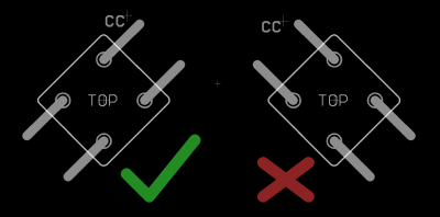
- Get the board as flat as possible, rear side facing up. If the LEDs protrude through the PCB cutouts, they will prevent the switches from being soldered in later.
- Identify the LED cathode and place it in the 45° hole with the cathode aligned with the common cathode (CC) pin.
- Stating the obvious: the LED legs should be pointing up!
- Using a screwdriver or other tool, bend the LED legs down, first against the body then so the leg runs flat against the pad.
- You may wish to leave the cathode pins unbent for now, as these should either be soldered carefully so the switch can still go in or simply left until it is time to install the switches.
- Probably bend all of the LEDs first before soldering any.
- Solder at least the three anode pins, again making sure that no LED protrudes through to the front side of the board and that the cathodes are in the correct positions.
Transistors
- Transistors T9-16 (BC808 PNP) are soldered on the top side of the board. When the whole thing is assembled, these will not be accessible, so it's important to do them right.
- Don't mix them up with the BC818 NPN transistors!
- Transistors mount square on. Don't try to mount at a funny angle!
Bottom-side components
- SMT resistors
- Now you can use the BC818s! Note they are distributed across the board.
- Resistors R18-25 adjacent to the transistors can be omitted
- ICs1-5. Note that the 595s point in a different direction to the 165s!
- Diodes, apart from the one next to C6, which is omitted. Ensure the legs won't interfere with the Matias switches.
- THT resistors R1-16
- take special care with R2, R3, R13 and R14 that the legs are as short as possible (even top-solder them). The encoder legs from the PCB stacked above will come down here.
- pin headers (top side)
- resistor networks (bottom side). It's very important to have the pin 1 dot aligned with the silkscreen marking
License
Currently the design is © 2017 antilog devices with all rights reserved; all documentation is CC BY-NC-SA 3.0.