This is an old revision of the document!
Table of Contents
Standard 220mm wide modules
VLR-3x8But
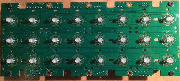
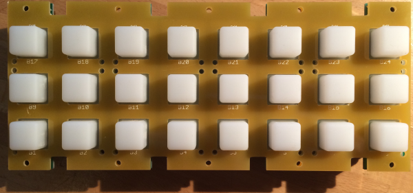
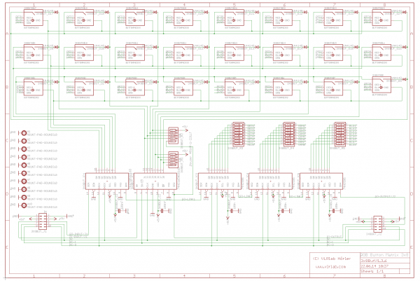
A PCB to add 24 Buttons with RGB LEDs for each.
Eagle Files: https://github.com/novski/Midibox/tree/master/VLR-3x8but
BOM
BIll of Material
Allways look for the cheapest seller, the Price may vary heavy!!! And look for Local dealers preferred. http://www.midibox.org/dokuwiki/doku.php?id=where_to_order_components
The Buttons
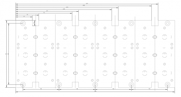
I thaught a long time about how to make a Button PCB that does not explode in material cost. The best solution was to buy rubberbuttons from Sparkfun and cut them because the with of Fadercore is fixed by the minimal width of 8 Oleds side by side… 220mm in width / 8 makes a 27.5mm grid. What a pity that the Sparkfun pads are premade with a 25mm grid…
you will need two of them: https://www.sparkfun.com/products/7835
The other Materials: Mouser
- 2x10pin Header, 517-30310-6002
- 5x100nF,594-K104K15X7RF53K2
- 2x10k, 774-77061103P
- 3x220R, 652-4816P-T1LF-220
- 1x74HC165D, 771-HC165D652
- 4x74HC595D, 771-74HC595D
- 24xLED RGB, 604-WP154A4SUREQBFZW
Project Order Basket on Mouser: fadercore_-_vlr-3x8but
The PCB is available under: http://vlrlab.com/lang/17-8enc.html
- 8 Encoder, 652-PEL12T4226FS1024 not on Projectlist because i deliver cheaper and with cap included..
The Encoder on VLRlabs.com https://www.vlrlab.com/encoder/13-bourns-rgb-led-encoder.html
How to get Started
If its your first SMD soldering you can follow this on t1:58 : http://www.youtube.com/watch?v=5uiroWBkdFY I recommend to not buy solder paste, instead buy some flux-paste like this on Mouser: 590-8341-10ML
Prepare the PCB
Start with the SMD parts and then go on the the conventional parts also on the Bottom side. Don't forget the R11,12,13. Then go on with the Topside and the LEDs before soldering the Encoder as last. Check the Connections with a Lens.
Prepare the Connection
Connect the core on J8/9 to J1 of the VLR-8Enc board.
Test it in MIOS
To make it work with MIOS .NGC File we need to know how the shift-registers are connected.
Inputs:
1# Encoder 1-4
2# Encoder 5-8
3# Encoder Button 1-8
Outputs:
1# RED Shaft LED 1-8
2# GREEN shaft LED 1-8
3# BLUE shaft LED 1-8
4# LED Ring Row 1-8
5# LED Ring Selct 1-8
6# LED Ring Select 9-11
Assuming that the VLR-8Enc is the first device on the chain of J8/9 we need to configure it like this:
RESET_HW
LCD “%C”
# Encoder configuration
ENC n= 1 sr=1 pins=0:1 type=detented2
ENC n= 2 sr=1 pins=2:3 type=detented2
ENC n= 3 sr=1 pins=4:5 type=detented2
ENC n= 4 sr=1 pins=6:7 type=detented2
ENC n= 5 sr=2 pins=0:1 type=detented2
ENC n= 6 sr=2 pins=2:3 type=detented2
ENC n= 7 sr=2 pins=4:5 type=detented2
ENC n= 8 sr=2 pins=6:7 type=detented2
# LEDring configuration
DOUT_MATRIX n= 1 rows=16 mirrored_row=0 inverted_sel=1 sr_dout_sel1= 4 sr_dout_sel2= 0 sr_dout_r1= 5 sr_dout_r2= 6
# Encoder events
EVENT_ENC id= 1 fwd_id=LED_MATRIX:1 type=CC chn= 1 cc= 24 lcd_pos=1:1:2 label=“^std_enc” LED_MATRIX_PATTERN=2
EVENT_ENC id= 2 fwd_id=LED_MATRIX:2 type=CC chn= 1 cc= 25 lcd_pos=2:1:2 label=“^std_enc” LED_MATRIX_PATTERN=2
EVENT_ENC id= 3 fwd_id=LED_MATRIX:3 type=CC chn= 1 cc= 26 lcd_pos=3:1:2 label=“^std_enc” LED_MATRIX_PATTERN=2
EVENT_ENC id= 4 fwd_id=LED_MATRIX:4 type=CC chn= 1 cc= 27 lcd_pos=4:1:2 label=“^std_enc” LED_MATRIX_PATTERN=2
EVENT_ENC id= 5 fwd_id=LED_MATRIX:5 type=CC chn= 1 cc= 28 lcd_pos=5:1:2 label=“^std_enc” LED_MATRIX_PATTERN=2
EVENT_ENC id= 6 fwd_id=LED_MATRIX:6 type=CC chn= 1 cc= 29 lcd_pos=6:1:2 label=“^std_enc” LED_MATRIX_PATTERN=2
EVENT_ENC id= 7 fwd_id=LED_MATRIX:7 type=CC chn= 1 cc= 30 lcd_pos=7:1:2 label=“^std_enc” LED_MATRIX_PATTERN=2
EVENT_ENC id= 8 fwd_id=LED_MATRIX:8 type=CC chn= 1 cc= 31 lcd_pos=8:1:2 label=“^std_enc” LED_MATRIX_PATTERN=2
# Encoder Buttons
EVENT_BUTTON id=117 hw_id=17 fwd_id=LED:8 type=cc chn=1 cc=15 range=0:127 button_mode=OnOff lcd_pos=1:1:3 label=“R^std_btn”
EVENT_BUTTON id=117 hw_id=17 fwd_id=LED:16 type=cc chn=1 cc=15 range=0:127 button_mode=OnOff lcd_pos=1:1:4 label=“G^std_btn”
EVENT_BUTTON id=117 hw_id=17 fwd_id=LED:24 type=cc chn=1 cc=15 range=0:127 button_mode=OnOff lcd_pos=1:1:5 label=“B^std_btn”
EVENT_BUTTON id=118 hw_id=18 fwd_id=LED:7 type=cc chn=1 cc=15 range=0:127 button_mode=OnOff lcd_pos=2:1:3 label=“R^std_btn”
EVENT_BUTTON id=118 hw_id=18 fwd_id=LED:15 type=cc chn=1 cc=15 range=0:127 button_mode=OnOff lcd_pos=2:1:4 label=“G^std_btn”
EVENT_BUTTON id=118 hw_id=18 fwd_id=LED:23 type=cc chn=1 cc=15 range=0:127 button_mode=OnOff lcd_pos=2:1:5 label=“B^std_btn”
EVENT_BUTTON id=119 hw_id=19 fwd_id=LED:6 type=cc chn=1 cc=15 range=0:127 button_mode=OnOff lcd_pos=3:1:3 label=“R^std_btn”
EVENT_BUTTON id=119 hw_id=19 fwd_id=LED:14 type=cc chn=1 cc=15 range=0:127 button_mode=OnOff lcd_pos=3:1:4 label=“G^std_btn”
EVENT_BUTTON id=119 hw_id=19 fwd_id=LED:22 type=cc chn=1 cc=15 range=0:127 button_mode=OnOff lcd_pos=3:1:5 label=“B^std_btn”
EVENT_BUTTON id=120 hw_id=20 fwd_id=LED:5 type=cc chn=1 cc=15 range=0:127 button_mode=OnOff lcd_pos=4:1:3 label=“R^std_btn”
EVENT_BUTTON id=120 hw_id=20 fwd_id=LED:13 type=cc chn=1 cc=15 range=0:127 button_mode=OnOff lcd_pos=4:1:4 label=“G^std_btn”
EVENT_BUTTON id=120 hw_id=20 fwd_id=LED:21 type=cc chn=1 cc=15 range=0:127 button_mode=OnOff lcd_pos=4:1:5 label=“B^std_btn”
EVENT_BUTTON id=121 hw_id=21 fwd_id=LED:4 type=cc chn=1 cc=15 range=0:127 button_mode=OnOff lcd_pos=5:1:3 label=“R^std_btn”
EVENT_BUTTON id=121 hw_id=21 fwd_id=LED:12 type=cc chn=1 cc=15 range=0:127 button_mode=OnOff lcd_pos=5:1:4 label=“G^std_btn”
EVENT_BUTTON id=121 hw_id=21 fwd_id=LED:20 type=cc chn=1 cc=15 range=0:127 button_mode=OnOff lcd_pos=5:1:5 label=“B^std_btn”
EVENT_BUTTON id=122 hw_id=22 fwd_id=LED:3 type=cc chn=1 cc=15 range=0:127 button_mode=OnOff lcd_pos=6:1:3 label=“R^std_btn”
EVENT_BUTTON id=122 hw_id=22 fwd_id=LED:11 type=cc chn=1 cc=15 range=0:127 button_mode=OnOff lcd_pos=6:1:4 label=“G^std_btn”
EVENT_BUTTON id=122 hw_id=22 fwd_id=LED:19 type=cc chn=1 cc=15 range=0:127 button_mode=OnOff lcd_pos=6:1:5 label=“B^std_btn”
EVENT_BUTTON id=123 hw_id=23 fwd_id=LED:2 type=cc chn=1 cc=15 range=0:127 button_mode=OnOff lcd_pos=7:1:3 label=“R^std_btn”
EVENT_BUTTON id=123 hw_id=23 fwd_id=LED:10 type=cc chn=1 cc=15 range=0:127 button_mode=OnOff lcd_pos=7:1:4 label=“G^std_btn”
EVENT_BUTTON id=123 hw_id=23 fwd_id=LED:18 type=cc chn=1 cc=15 range=0:127 button_mode=OnOff lcd_pos=7:1:5 label=“B^std_btn”
EVENT_BUTTON id=124 hw_id=24 fwd_id=LED:1 type=cc chn=1 cc=15 range=0:127 button_mode=OnOff lcd_pos=8:1:3 label=“R^std_btn”
EVENT_BUTTON id=124 hw_id=24 fwd_id=LED:9 type=cc chn=1 cc=15 range=0:127 button_mode=OnOff lcd_pos=8:1:4 label=“G^std_btn”
EVENT_BUTTON id=124 hw_id=24 fwd_id=LED:17 type=cc chn=1 cc=15 range=0:127 button_mode=OnOff lcd_pos=8:1:5 label=“B^std_btn”
LED_MATRIX_PATTERN n=2 pos= 0 pattern=1111110000000000
LED_MATRIX_PATTERN n=2 pos= 1 pattern=0111110000000000
LED_MATRIX_PATTERN n=2 pos= 2 pattern=0011110000000000
LED_MATRIX_PATTERN n=2 pos= 3 pattern=0001110000000000
LED_MATRIX_PATTERN n=2 pos= 4 pattern=0001110000000000
LED_MATRIX_PATTERN n=2 pos= 5 pattern=0000110000000000
LED_MATRIX_PATTERN n=2 pos= 6 pattern=0000010000000000
LED_MATRIX_PATTERN n=2 pos= M pattern=0000111000010000
LED_MATRIX_PATTERN n=2 pos= 8 pattern=0000010000000000
LED_MATRIX_PATTERN n=2 pos= 9 pattern=0000011000000000
LED_MATRIX_PATTERN n=2 pos=10 pattern=0000011000000000
LED_MATRIX_PATTERN n=2 pos=11 pattern=0000011100000000
LED_MATRIX_PATTERN n=2 pos=12 pattern=0000011110000000
LED_MATRIX_PATTERN n=2 pos=13 pattern=0000011110000000
LED_MATRIX_PATTERN n=2 pos=14 pattern=0000011111000000
Im using my VLR-8oDisp board to show the Values of every item. You can change it to any other type of Display-setting… lcd_pos=6:1:5 {6=Display number : 1= X-axis : 5= Y-Axis (row)}


