This is an old revision of the document!
Table of Contents
MCAN, MIDIbox Controlled Area Network
Low cost MIDI(Native) Network using CAN, this is MCAN…
Why?
Because we CAN … ha! I'll stop joking. :)
At home I have no space to put my equipment in the middle of the room and maintain an access space behind to rewire the machines for each session. It is boring having to do it every time, especially to waste time and lose inspiration between two takes.
For Audio, no problem, I've got a good and very large patchbay.
For MIDI I've got two MIDITimePiece units, they are enough for a music piece, but don't have enough IO to avoid rewiring. And this is just for MIDI.
I searched for a long time for a way to interconnect all the control signals of my home studio, to make communication between them intelligent, in the configuration I want and whatever they are, MIDI, CV, Gate, Sync 24 / 48ppqn etc. …
A Core is already able to manage all of these controls…
So I need something like a network or a buss between the Cores. Then a more or less dedicated protocol. And this must be cheap!
…I searched then “I called a friend” and he said “MBNET”…
Ok!?. I know MBNET but for me it's a legacy of MIOS8, it just allows to interconnect Cores for a single application e.g. MB-SID.
Something obsolete since a MIOS32 Core is in fact able to drive several modules at once. But I still took a look.
I read everything I found about MBNET within the community and I focused on the device directly.
It was a bit difficult to dig in the beginning, CAN was a bit of a mystical thing.
Now I understand more and my friend still does not imagine how right he was!
CAN: the basics
“The CAN bus was developed by BOSCH as a multi-master, message broadcast system that specifies a maximum signaling rate of 1 megabit per second (bps). Unlike a traditional network such as USB or Ethernet, CAN does not send large blocks of data point-to-point from node A to node B under the supervision of a central bus master. In a CAN network, many short messages are broadcast to the entire network, which provides for data consistency in every node of the system. Once CAN basics such as message format, message identifiers, and bit-wise arbitration…”
From T.I. Introduction to the Controller Area Network (CAN).
The Buss
There's two ways to connect the nodes on the buss:
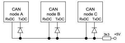
A single wire, it's what TK did for MBNET:
There's no transceiver, all the controllers are connected on a single line, this line is limited to 20cm (maybe more), we need some diodes and one resistor to emulate what the absent transceiver normally does. This is fine to interconnect multiple Cores in the same device (enclosure).
With transceivers on a 2 wire buss. All nodes are in parallel over the buss.
This allows very long cabling, some hundred meters can be achieved depending on the speed.
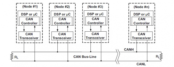
For both connection models, each Node(Device) connected to the buss can transmit or receive data. How is this possible?
In each controller there's a mechanism (it's hardware), when one device is transmitting the others know it and they are placed in receive mode until the transmitting node releases the bus. If more than one device wants to take over transmission at the same time, another mechanism (always hardware) arbitrates and will allow only one device to transmit, delaying the others.
The Frame
CAN does not transmit bytes like UART or SPI but packets or frames like Ethernet.
Each packet has:
- A Start Of Frame bit.
- An identifier (arbitration) field, which can have 2 forms: Standard (11bit) or Extended (29bit).
- A control field where the amount of data (0-8), type/format of message are determined.
- A data field, from 0-8 bytes maximum.
- A CRC field, to check the validity of each received packet.
- Some acknowledgement bits.
- And finally an End Of Frame field.
The arbitration (ID) field
This is the most important part, take your time to understand this mechanism.
This will dictate the behaviour of the packets over the buss.
In transmit this is where the arbitration (priority) packets is done. This part of the frame determines what device is permitted to transmit data first and what will be the next available device. This is the smartest part of CAN
What happens when two or more nodes attempt to transmit at the same time?
The table shows three nodes attempting to transmit simultaneously, each starting with dominant 0s. When a node transmits a recessive 1 but sees that the bus remains at dominant 0, it realises there is a conflict, ceases to transmit and waits for the next opportunity to transmit.
This allows for prioritisation of the messages depending on the composition of the ID and at the hardware level. Good :)
 In this way the node with the lowest value ID takes priority and is permitted to transmit the rest of the frame.
In reception this field has another function: each CAN has a hardware filtering mechanism (more or less nicely implemented). This allows the CAN to protect the software from incoming packets it does not need, those that are not intended for a particular device. This should be very useful to avoid useless software processing–Core processing in fact.
When a packet is received, the CAN will first check if it is valid (CRC etc.) then it will propagate its ID through a bank of filters. Each filter includes a mask and the ID required.
For each filter it will first apply the mask to the incoming ID; this will reveal which bits will be tested and which ones will be ignored. Then the new value is compared with the stored one in the filter. If the masked bits are equal to those of the filter it releases the packet and stores it in a buffer. Otherwise the packet is rejected and simply ignored.
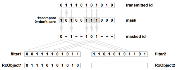 Left filter allows the packet to go into the buffer, right filter rejects it.
Because of this, like for Ethernet, a message can be “broadcast” or “unicast”.
Better, it can control a group of nodes if their IDs are consecutive (same MSB). That's fine :)
The arbitration field has two possible formats, i.e., two sizes:
- The Standard ID format (CAN 2.0A & CAN 2.0B), which supports 11-bit identifiers.
- The Extended ID format (CAN2.0B only) which supports 29-bit identifiers, with the eleven most important bits common to those of the Standard format.
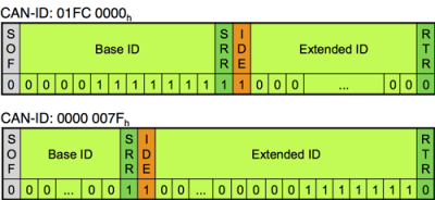 Two examples of Extended (29bit) ID.
We can mix both formats on the same buss without any trouble.
There's a bit in the control field of the packet that indicates the format named “IDE.” Standard=0, Extended=1.
In a 29 bit ID this IDE bit is part of the arbitration and causes a standard ID to gain priority over an Extended one (0 always wins).
Because of this feature there's also two sizes of filter available.
Additional RTR and SSR bits for message type.
- The RTR bit, indicates the type of message: (0) for data message, (1) for request message.
- The additional SSR bit (Extended ID only), is for message type too, whereby the position in the frame allows it to take priority over the IDE bit if necessary.
This bits are part of the arbitration but not part of the ID; they are control bits.
The control field
Here we will specify the type of format, type of message and data length.
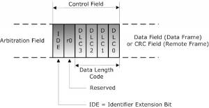
- The IDE bit, (0) ID is Standard(11bit), (1) Id is Extended(29bit).
- The 4 DLC bits, this is the Data Length Code(from 0 to 8).
The data field
This the data area, 0-8 bytes wide; length is indicated by DLC.
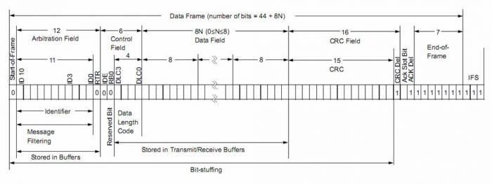 A more detailed Standard frame.
Upon a received packet, the number of bytes must match DLC to avoid a CRC error.
The CRC field
CRC stands for Cyclic Redundancy Check, which is used for error detection!
The Ack. bits
All nodes that receive a frame without finding any errors transmit a dominant 0 (acknowledge), which overrides a recessive 1 sent by the transmitter. If the transmitter detects a recessive 1, it knows that the frame was not received correctly and can retry to send the message.
Buss error handling
This is another beautiful feature of this amazing buss.
It has the ability to self-diagnose and repair data errors.
With the Ack. bit, the transmitter knows if the message was received and if the frame is valid. In case of an error the receiver(s) do not toggle the Ack. bit, and will initiate an automatic retry. Then a single error can be easily fixed.
When too many consecutive errors occur the device can decide to cease transmission. This avoids having a faulty transmitter corrupting the whole bus. The silent device continues to receive data and the others act as normal.
The baudrate
Okay, CAN is a robust buss, a ready to use protocol. We just have to decide what is system parameters to set. But, what about speed?
For a Standard packet, number of bits ≈ 44 + 8*n.
For an Extended packet, number of bits ≈ 65 + 8*n.
where n is the number of Data bytes.
Baudrate (BR) is maximum of 2MHz. The frame time t is
tStandard = (44 + 8*n) / BR tExtended = (65 + 8*n) / BR
Time for a Standard 8 byte packet ≈ 54 us.
⇒For this kind of packet, we should theoretically achieve a rate of 18518 frames/s.
Time for the smallest Standard no-data packet ≈ 22 us.
⇒rate is 45454 frames/s.
Time for the largest Extended 8 byte packet ≈ 64.5 us.
⇒rate is 15503 frames/s.
It depends on the size of the frames, of the protocol we use and this has to be optimized.
This is not bad… tt deserved to be tested. This is not comparable with a regular MIDI connector, but one MIDI byte takes 320us, it's almost 1ms for a voice event like Note or CC.
Conclusion
“CAN is ideally suited in applications requiring a large number of short messages with high reliability in
rugged operating environments. Because CAN is message based and not address based, it is especially well suited when data is needed by more than one location and system-wide data consistency is mandatory. Fault confinement is also a major benefit of CAN. Faulty nodes are automatically dropped from the buss, which prevents any single node from bringing a network down, and ensures that bandwidth is always available for critical message transmission. This error containment also allows nodes to be added to a buss while the system is in operation, otherwise known as hot-plugging.”
From T.I. Introduction to the Controller Area Network (CAN) again.
References
Vector CAN Introduction
kvaser CAN Protocol Tutorial
CAN Filter & Mask Tutorial
CAN Protocol Decoding
CAN Data Link Layer

MCAN
Should we walk in the footsteps of MBNET?..
Let's take two minutes to consider the implementation of CAN in the MBNET.
It's is a legacy function of MIOS8 but TK has already migrated the MBNET to MIOS32. MB-SID, MB-FM and some other applications support it.
These are enough to find inspiration, so I explored starting from known applications. I looked at how it was implemented in the code.
- Master-slave philosophy.
- An ID between 0-127 is used for addressing.
- The messages are a type of “TCP”: send a request, get a reply. This is underpinned by a software acknowledge.
- The commands are specific to the application.
- It only uses the Extended ID.
- The reception registers are polled by a dedicated task, which scans all other nodes simultaneously.
- There is only one filter (the address); arbitration prioritises the nodes with decreasing ID.
- Messages are only 'unicast' and not 'broadcast.'
On one hand I have MBNET, ready to be used. The hardware is not implemented deeply, but it is enough for existing apps.
However, the commands are quite specific to the tasks and to write new ones will be difficult if the new application is significantly different those that exist. The CAN Controller driver is part of the application, not a ready-to-use peripheral like the USB or the UART.
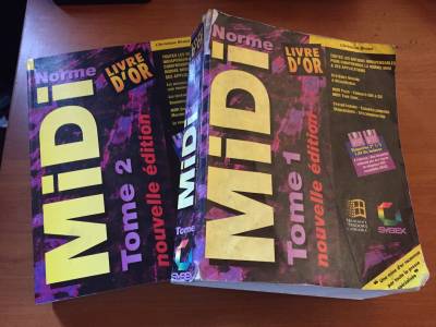
On the other hand there is my Bible, surely yours too, even if this one is French.
That is what I want! It can carry all the controls I need. Moreover we all know it by heart.
This was the starting point. Using CAN to carry the MIDI natively.
Also optimising the CAN hardware features for a pure MIDI purposes.
...Introduction to a native MIDI over the buss.
The MIOS32 is a native MIDI processor and some of its peripheral are tagged 'available' for MIDI communication, they are listed in the mios32_midi_port_t enum typedef, each peripheral type has its own number of ports:
/////////////////////////////////////////////////////////////////////////////
// Global Types
/////////////////////////////////////////////////////////////////////////////
typedef enum {
  DEFAULT    = 0x00,
  MIDI_DEBUG = 0x01,

  USB0 = 0x10,
  ...
  USB7 = 0x17,

  UART0 = 0x20,
  ...
  UART3 = 0x23,

  IIC0 = 0x30,
  ...
  IIC7 = 0x37,

  OSC0 = 0x40,
  ...
  OSC7 = 0x47,

  SPIM0 = 0x50,
  ...
  SPIM7 = 0x57,

} mios32_midi_port_t;
The best case is to implement CAN as a regular MIDI port within MIOS32_MIDI. Just like other ports it must be easy for the user, they will transmit thru the common MIOS32_MIDI_Send and Receive MIDI events in the regular APP_Notify_xxx callbacks.
I did the job, the CAN controller is fully implemented as a ready-to-use peripheral in MIOS32,
once all the CAN features were ready, the MIDI layer was added too, and the MCAN is now in the list of the 'available' MIDI pipes, as a 16 ports connection
  ...
  SPIM7 = 0x57,

  // New MCANx virtual Ports.
  MCAN0 = 0x60,
  ...
  MCAN15 = 0x6f

} mios32_midi_port_t;
But before any MIDI features we need the MIOS32 driver for that CAN controller…
MIOS32_CAN implementation
CAN controller as a generic peripheral in MIOS32.
MIOS32_CAN feature is only compilable under STM32F4.
I put this limitation then you will only find the “mios32_can.c” file in the STM32F4 folder.
If you really want to use it I have a working draft of the file for the LPC1769.
And limitation can be changed here:
// number of CAN interfaces (0..2)
#if defined(MIOS32_BOARD_STM32F4DISCOVERY) || defined(MIOS32_BOARD_MBHP_CORE_STM32F4)
#ifndef MIOS32_CAN_NUM
#define MIOS32_CAN_NUM 1
#else
#if MIOS32_CAN_NUM >2
#define MIOS32_CAN_NUM 2
#endif
#endif
#else
#define MIOS32_CAN_NUM 0
# warning "Unsupported MIOS32_BOARD selected!"
// because of MIDI Area Network Id arbitration and filtering, only STM32F4 is supported.
#endif
There's some huge differences between the two processors CAN controllers, the biggest are:
- On the STM32F4, CAN interrupt mechanism is used, on the LPC the CAN buffers are polled.
- The two types of processor have totally different CAN filtering system.
For some good technicals reasons, I have to admit that I spent more time on the STM32F4 based one
Maybe better to choose the STM32F4 for your own MCAN application…
There's two CAN controller on a STM32F4.
Both are implemented even if the second has its dedicated pins used by legacy SRIO port[J8/9]
The work is done now what you want to know is…
How to use MIOS32_CAN.
Just add this lines in your mios32_config.h(your app).
There a few options you can override here…
/* the use of CAN Controller must be precised.
 */
#define MIOS32_USE_CAN

/* The two CAN Controller are now fully implemented in MIOS32
 Can be use for other purpose(not MCAN)
 Note: Only CAN1 can be used by the MIDI MCAN layer.
 Number of used CAN can be precised(0...2), default is 1
 */
//#define MIOS32_CAN_NUM 1

/* Alternate function pin assignement for CAN2.
 0: CAN2.RX->PB5, CAN2.TX->PB6
 1: CAN2.RX->PB12, CAN2.TX->PB13
 */
//#define MIOS32_CAN2_ALTFUNC     0
Congratulation! Your CAN Controller is ready to work!!…. But this is just an empty pipe for the moment…
You can create your own protocol to use it. e.g. the protocol part of the MBNET can be adapted to use it easily.
Here the list of the shared functions.
This is a part of the common mios32_can.h file
This might be submitted to some minor changes in the future…
/////////////////////////////////////////////////////////////////////////////
// Prototypes
/////////////////////////////////////////////////////////////////////////////

extern s32 MIOS32_CAN_Init(u32 mode);

extern s32 MIOS32_CAN_IsAssignedToMIDI(u8 can);

extern s32 MIOS32_CAN_InitPort(u8 can, u8 is_midi);
extern s32 MIOS32_CAN_InitPortDefault(u8 can);
extern s32 MIOS32_CAN_InitPeriph(u8 can);
extern s32 MIOS32_CAN_Init32bitFilter(u8 bank, u8 fifo, can_ext_filter_t filter, u8 enabled);
extern s32 MIOS32_CAN_Init16bitFilter(u8 bank, u8 fifo, can_std_filter_t filter1, can_std_filter_t filter2, u8 enabled);
extern s32 MIOS32_CAN_InitPacket(can_packet_t *packet);

extern s32 MIOS32_CAN_RxBufferFree(u8 can);
extern s32 MIOS32_CAN_RxBufferUsed(u8 can);
extern s32 MIOS32_CAN_RxBufferGet(u8 can, can_packet_t *p);
extern s32 MIOS32_CAN_RxBufferPeek(u8 can, can_packet_t *p);
extern s32 MIOS32_CAN_RxBufferRemove(u8 can);
extern s32 MIOS32_CAN_RxBufferPut(u8 can, can_packet_t p);

extern s32 MIOS32_CAN_TxBufferFree(u8 can);
extern s32 MIOS32_CAN_TxBufferUsed(u8 can);
extern s32 MIOS32_CAN_TxBufferGet(u8 can, can_packet_t *p);
extern s32 MIOS32_CAN_TxBufferPutMore_NonBlocking(u8 can, can_packet_t* p,u16 len);
extern s32 MIOS32_CAN_TxBufferPutMore(u8 can, can_packet_t *packets, u16 len);
extern s32 MIOS32_CAN_TxBufferPut_NonBlocking(u8 can, can_packet_t p);
extern s32 MIOS32_CAN_TxBufferPut(u8 can, can_packet_t p);

extern s32 MIOS32_CAN_BusErrorCheck(u8 can);

extern s32 MIOS32_CAN_Transmit(u8 can, can_packet_t p, s16 block_time);

extern s32 MIOS32_CAN_ReportLastErr(u8 can, can_stat_err_t* err);
extern s32 MIOS32_CAN_ReportGetCurr(u8 can, can_stat_report_t* report);
extern s32 MIOS32_CAN_ReportReset(u8 can);
I made my best to respect the OS and properly insert this part.
This is type definition of a generic CAN Packet(a frame) structure and its substructures:
This should never change any more…
// CAN mailboxes packet
typedef struct can_packet_t {
  can_ext_id_t id;      // sub struct contains the 29 bit extended frame(packet) id
  can_ctrl_t ctrl;      // sub struct contains special data like the dlc(data length)
  can_data_t data;      // sub struct contains the datas(8 bytes max)
} can_packet_t;
Structure is used for both extended and standard frame, the ext_id contains the std_id.
Representation of an empty CAN Packet(frame) you can now use.
MIOS32_CAN_MIDI implementation
Package and Packet
Like the others MIDI peripherals, we need a bridge between our new CAN features(mios32_can.c/h) and the MIDI process(mios32_midi.c/h)
This is the new files:
- mios32_can_midi.c
- mios32_can_midi.h.
Here, the composition of the packet, the use of its hardware features(arbitration and filter) are decided.
The included functions in this files are called by the MIOS32_MIDI functions and provide the packeting/packaging process.
In (MIOS32_MIDI) functions, the message is not a packet but a smaller “package”, mios32_midi_package_t
This package is a 32bits word, is composed by the regular MIDI datas(3 bytes max) and in first byte there's two more nibbles, the cable for the port number and type for events filtering/size and Sysex packaging. This two fields are very useful.
The cable allows to get up to 16 virtual ports(a nibble), this is up to 256 MIDI Channels. This will be helpful to target the voices of an instrument from the tracks of a sequencer. And provide an internal minimal routing.
The 16 ports share the whole CAN bus bandwidth.
The type field is better to use than the regular midi status, Types are provided with their respective MIDI bytes number array and are enough ordered to match the natural arbitration. e.g. a real-time event must take priority over any other events. Just like a CC must cede priority to a Note etc… Remember, for CAN arbitration the smallest value wins.
Notes: Real-time events are forced to type 0x5 during MCAN transport, they appear to become type 0xf sometimes…
//! this global array is read from MIOS32_MIDI to
//! determine the number of MIDI bytes which are part of a package(or packet)
const u8 mios32_midi_pcktype_num_bytes[16] = {
  0, // 0: invalid/reserved event
  0, // 1: local command
  2, // 2: two-byte system common messages like MTC, Song Select, etc.
  3, // 3: three-byte system common messages like SPP, etc.
  3, // 4: (!)SysEx starts
  1, // 5: (!)Single-byte system common message
  2, // 6: (!)SysEx continues
  3, // 7: (!)SysEx ends
  3, // 8: Note Off
  3, // 9: Note On
  3, // a: Poly-Key Press
  3, // b: Control Change
  2, // c: Program Change
  2, // d: Channel Pressure
  3, // e: PitchBend Change
  1  // f: single byte

  //which is normally
  3, // 4: SysEx starts or continues
  1, // 5: Single-byte system common message or sysex sends with following single byte
  2, // 6: SysEx sends with following two bytes
  3, // 7: SysEx sends with following three bytes
};
Sysex is transmitted by 8 bytes data packets over the MCAN then the Sysex types are just used differently,
they present the first and last packets independently from the others.
Type and Cable(one byte)are enough for a regular and working network. They are the standard part of the frame Id.

This is MCAN in Basic Mode: it sends the package to every node on the buss and receive from them too. It will behave just the same as other MIDI ports. There's no traffic optimization but the Standard Id packets are small!
Once you decide to use it, it's ready, there's nothing more special or advanced thing to do…
…Of course if it exists a Basic Mode there's an advanced one, the Enhanced Mode use the Extended Id Packet but always with the common Standard Id arbitration(Type and Cable fields). The 18 bits extension contains extras informations, with it we will be able to use the MCAN as a forwarder. Hardware filter will be used if necessary as a layering or isolation and finally optimize the traffic…
before building more sophisticated App, let's talk about the Basic Mode, first…
Basic Mode
This is the default mode, the funny one, just interconnect some Cores in parallel with J18 and they are able to communicate in MIDI. Easy.
In this mode:
- MCAN acts like others MIDI ports, it behaves the same.
- You can use 16 ports from MCAN0 to MCAN15.
- The Node Id, Id of the Core other the Buss doesn't matter.
- The MCAN can be easily added to any of your existing App.
- The messages are in broadcast over the buss, no filtering and no sophisticated features.
- There's no buss management to optimize the bandwidth but the MIDI packets are short.
You will need 5 minutes to make it work and start your multicore App.
Standard Packet in Basic Mode
Even if the MCAN make the MIDI packet for you, let me show you some of them:
The IDE bit in frame is always 0, cause we only use the Standard Id Packet, the Type and the Cable must be placed in the Id.
The DLC, indicates the number of necessary MIDI bytes and is automatically set.
It's very simple:
- Type and Cable byte ⇒ in the Standard Id.
- The regular MIDI package ⇒ in the datas field.
- the regular MIDI bytes number ⇒ in the DLC field.
The Sysex messages are an exception for the DLC, we makes packets of 8 bytes(max) with it, and we mark the packets as Starts, Continues or Ends in the Type field, using the code 0x4, 0x6 and 0x7.
Real-time messages
1, // 5: Single-byte system common message
- Type is set to 0x5(Single-byte system common message).
- The regular MIDI byte number is 1.
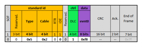
e.g. MIDI Clock:
an 0xf8 MIDI Clock over the port MCAN2.
Voice messages
  3, // 8: Note Off
  3, // 9: Note On
  3, // a: Poly-Key Press
  3, // b: Control Change
  2, // c: Program Change
  2, // d: Channel Pressure
  3, // e: PitchBend Change
- Packet Type is equal to the regular MIDI status event type.
- There is data(2 or 3 bytes), where the data length depends on the exact type.
e.g. Note-On, 3 bytes:
Note: D#2, vel: 100 on MCAN6/Channel 4.
e.g. Program Change, 2 bytes:
Program: 33, on MCAN3/Channel 13.
SysEx messages
  3, // 4: SysEx starts
  2, // 6: SysEx continues
  3, // 7: SysEx ends
- 8 bytes packets are automatically formed.
- The first and last packets are recognizable.
- Last packet has a variable length depending on the remaining bytes.
- Regular MIDI bytes number doesn't matter.
e.g. A 20 bytes SysEx stream:
First packet(type 0x4) where the first data byte is the SOX(0xf0).
Second packet(type 0x6).
Last packet contains 4 bytes, last byte is the EOX(0xf7).
A 1024 byte stream takes 330ms over a regular MIDI, the same stream takes 8,5ms over MCAN.
Basic Mode, declare and use
Just add this lines in your mios32_config.h(your app).
/* the use of CAN Controller must be precised.
 */
#define MIOS32_USE_CAN

/* CAN1 is MCAN must be precised.
 */
#define MIOS32_USE_CAN_MIDI

/* Number MCAN MIDI Ports, default and max is 16
 */
#define MIOS32_CAN_MIDI_NUM_PORTS 16
Done! MCAN is ready!
A basic example
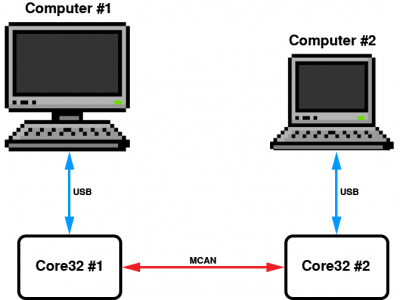
For this example we will use 2 Core to get an 8 MIDI ports link between 2 different computers.
The USB limits the link to 8 MIDI ports. Don't forget to declare it too.
/* the use of CAN Controller must be precised.
 */
#define MIOS32_USE_CAN

/* CAN1 is MCAN must be precised.
 */
#define MIOS32_USE_CAN_MIDI

/* Number MCAN MIDI Ports, default and max is 16
 */
#define MIOS32_CAN_MIDI_NUM_PORTS 8

// enable 8 USB MIDI ports
#define MIOS32_USB_MIDI_NUM_PORTS 8
Go in your App code and add this lines in your APP_MIDI_NotifyPackage:
/////////////////////////////////////////////////////////////////////////////
// This hook is called when a MIDI package has been received
/////////////////////////////////////////////////////////////////////////////
void APP_MIDI_NotifyPackage(mios32_midi_port_t port, mios32_midi_package_t midi_package)
{
  if((port & 0xf0) == MCAN0){
    // receive the voice messages from MCANx and forward it to the USBx
    MIOS32_MIDI_SendPackage(USB0 + (port & 0x0f), midi_package);

  }else if((port & 0xf0) == USB0){
    // filter for voice messages from USBx
    if(midi_package.type >= 0x8 && midi_package.type <= 0xe){
      // forward the voice messages to MCANx
      MIOS32_MIDI_SendPackage(MCAN0 + (port & 0x0f), midi_package);
    }
  }
}
Enhanced Mode
There are two CAN busses on a Core32. For STM32F4, CAN2 I/O is not easily accessible as it shares pins with very important ports of MIOS: J8/9, J19, J4B. However if I add one in software I must add the other too.
Another reason is that it maybe useful to use a Core as 'gateway' between two Busses (e.g. a multi-core device as a network).\\</del>
Except for SysEx, the messages will be 'UDP-like.' In MIDI, a machine doesn't answer back if a message is received, the same thing occurs with MCAN. And remember, there's already a hardware Ack. and an automatic retry for faulty packets.
Like regular UART, MCAN is hot-pluggable. I can remove or add a device on the buss. The buss doesn't fall and the other devices are back online once everything is reconnected and the buss is correctly terminated.
To get the maximum priority throughput, the MCAN status must be at the MSB of the ID… But we write 3 bits before this.
This gives us the possibility to override the status arbitration, or we can isolate groups of devices (8 max), which resembles 'VLAN'. Creating multiple virtual networks in the buss will not decrease the total bandwidth 
Three other bits are added after the status bit, which are used to extend the MIDI channels of voice messages. Applications could control an audio mixer or transport DMX data (lightning). Within a SysEx message they indicate which part of the stream the packet is (Start/Cont/End).
The group bit indicates that the destination ID is an address of a group of devices and not an individual device.
The group ID range is 0x80-0xef; 0xf0 to 0xff are reserved for special addresses like Broadcast(All) = 0xff.
With this composition of ID, we can now filter incoming messages by one or more fields. This shields the uC from messages it doesn't require.
We use the different frame format (length) depending on the MIDI message type.
This will optimise traffic on the buss.

