Table of Contents
IN PROGRESS
MIDIbox BLM 16x16+X PCB and case build guide
Introduction
In 2010, MIDIboxer TK. made huge waves with his BLM (button LED matrix) 16×16+X. Never before had we seen such a mangle of duo LEDs, verowire and shift registers. The monome had been known for several years prior, as had smaller matrices for the SEQ, but the 16×16+X was a step further with its colourful LEDs and dedicated column, row and shift button. Arguably these pioneering devices inspired widespread development in commercial products such as the Novation Launchpad and Ableton Push.
TK.'s prototype was only ever meant to be that. In his words it took 40 hours and he was never prepared to do the same work again. Although the unit still works some five years later, the point-to-point wiring is somewhat fragile and the cheap tactile buttons are unergonomic. There were a few attempts at full PCB solutions, but the scale of the project is fairly daunting and sadly none eventuated.
My interest in a fresh start was piqued upon hearing of adafruit's UNTZtrument, which uses their own 4*4 silicone button pads. Years back we had considered pads from Sparkfun and Livid, but adafruit's are significantly smaller and cheaper. Rubberised buttons also have the best tactile feeling and don't click when they're pressed. One issue was the small internal space inside the button (only accepting a 3mm LED) so it was determined from the start to go for an SMT solution.
Concept of the project
Initial development of the BLM was done by TK., as noted elsewhere. A 17*17 button array is scanned using SCALAR modules consisting of 74HC165 (DIN) and 74HC595 (DOUT) shift register chips, the latter as current sinks via BJT transistors. Additional 595 chips drive LED anodes, while the cathodes share the same sinks as before. In total five SCALAR modules are present, one for the left-most and bottom “extra” column and row, and four for the remaining blocks of 16×4.
In the BLM 16×16+X PCB, the matrix is fully connected and all SCALAR modules are on-board, allowing for a cleaner build with less wiring, less physical space required and better signal integrity. A 4-layer PCB was used with one layer dedicated to ground/0V. There was also space to include four 60mm sliders which allow for additional control. The serial chains are brought out by a MIDIbox-standard J8/9 2*5 DIL header with the SC (clock), RC (latch), DIN and DOUT signals, along with +5V and 0v/ground. These may be interfaced with a MBHP Core8 or Core32 module, but most users will stick to the tailor-made miniCore (see later).
The following circuit changes were made:
- RC termination possible for SC and RC lines, although it seems unnecessary to do so.
- Pull-down resistors on current sink transistor bases (important when bases are floating and should decrease power consumption).
- Schottky diodes from base to collector of current sink transistors. This helps to turn transistors “off” quicker and reduces “ghosting” in the matrix.
- Output enable (/OE) delay implemented on pin 13 of 74HC595 chips. At power up the series capacitor will charge, holding all outputs in a high impedance state to ensure all registers have been initialised. One delay circuit is provided for each SCALAR section.
For minimal external cabling, the BLM connects to a SEQ v4 via an 8-pin DIN connector. This combines MIDI in, MIDI out and power; the communications protocol sent and received by the BLM is standard MIDI. Most users will incorporate a Quad IIC board into their SEQ case, which is the simplest way to arrange the DIN8 connector, optocoupler and header pins.
Build guide
General considerations: read before building
- The 289 through hole diodes are the most tedious part of the build. They should be trimmed as short as possible before soldering from the rear (i.e. the same side as the component). If the legs protrude though too much then you'll have trouble getting the silicone button pads to sit flat. Note that it's not necessary to have the diode sitting flush to the PCB – in fact the diodes must be raised over most of the surface mount transistors.
- I suggest that the PCB is initially clamped (using a scrap piece of material to protect it from the clamp) to the work space, otherwise your parts may jump around if the board gets bumped. If it is truly flush with your bench it will also help to keep the diodes/solder from going through the plated holes. Try to protect the exposed button pads on the PCB top by using a piece of clean paper or other material; don’t damage the surface by scratching it.
- LEDs are a little bit sensitive; don’t heat them for more than about 2 seconds at a time and apparently they don’t like static discharges… As far as I know, the humidity warnings you get with them are only really applicable to oven reflow soldering.
- Rev 1.1 boards have quite small ground plane isolation, and the soldermask is somewhat prone to scratching. Take extra care when soldering capacitors and ICs that you don't accidentally short the +5V rail, as this will make troubleshooting difficult.
Parts list
The following parts are available from Mouser, you can try this shopping basket to save time.
http://www.mouser.com/ProjectManager/ProjectDetail.aspx?AccessID=e31c510729
                      Quantity  Recommended     Description
Resistors
660-MF1/4DC1002F      4	        4	        10k through hole
652-CR1206FX-1002ELF  41	100	        10k 1206
652-PTL45-15R0-103B2  4	        4	        10k slider, 15mm shaft, red LED
652-PTL45-10G0-102B2  -         -               1k  slider, 10mm shaft

Resistor networks
652-4816P-T2LF-10K    5	        6	        10k bussed (165 pullups)
652-4816P-1LF-1K      5	        6	        1k isolated (current sinks)
652-4816P-1LF-220     5	        6	        220R isolated (green LEDs, also red LEDs)
652-4816P-1LF-56      5	        6	        56R isolated (blue LEDs)

Capacitors
647-TVX1C471MAD	      1	        1	        470uF electrolytic axial
80-C1206C104K5R	      23	50	        100n ceramic 1206
647-F931C106MAA	      5	        10	        10uF tantalum 1206

Diodes
512-BAT54	      36	100	        Schottky diode SO-23
512-1N4148TR	      289	300	        1N4148 diode
78-LS4148-GS18	      5	        10	        4148 quadroMELF

LEDs
604-APTR3216ZGC	      289	300	        LED green 1206 reverse mount
604-APTR3216QBC/D     289	300	        LED blue 1206 reverse mount
604-APTR3216SURCK     -         -               LED red 1206 reverse mount

Transistors
512-BC81840MTF	      36	100	        NPN BJT SO-23

ICs
595-SN74LVC1G17DBVR   3	        10	        Schmitt trigger, overvoltage tolerant SO-23-5
595-SN74HC165DR	      5	        10	        74HC165D SOIC
595-SN74HC595DR	      15	20	        74HC595D SOIC

Connectors
523-T3507-000	      1	        1	        DIN 8 panel connector
523-T3504-001	      2	        2               DIN 8 plug
---                   2         -               2x5 DIL header male, snap from a larger piece
---                   1         -               2x5 IDC plug female (DIN8 <-> miniCore)

Hardware
---                   40cm      -               10-way ribbon cable
---                   20        -               M3 nut (stainless)
---                   20        -               M3 washer (stainless)
---                   1(+4)     -               M2 grub screw, 14 mm (stainless)
---                   1(+4)     -               M2 nut (stainless)
---                   1(+4)     -               M2 washer (stainless)
---                   2         -               M3 standoff, 12mm male-female
---                   8         -               M3 standoff, 25mm (for spacing PCB during building)

Buttons
---                   18(19)    -               adafruit 4x4 silicone

Spacer
---                   1         -               spacer cut from 3mm opaque acrylic
Parts notes
- You can choose either Blue+Green LEDs (recommended) or Blue+Red. You could interchange some Green for Red. Green+Red is not recommended as the colour mixing is poor.
- Slider height: I specified 15mm shaft sliders, you could change these for 10mm. 15mm will protrude 13mm out of the case, which might be a bit long. 10mm will only protrude 8mm, so they would be less likely to break off and will probably be a bit more sturdy. TK. suggests 1k should work, the others are too high in resistance to get good jitter-free values (10k sliders with the shorter shaft aren't readily available).
- You should use the indicated panel mount DIN, but a cheaper pair of DIN8 plugs might work.
- M2 hardware is a bit difficult to find in normal stores, but Boltbase on eBay has good deals.
Tools needed
- Soldering iron, I managed with a normal tip but it’s a bit tricky with some components
- Solder, probably leaded. 0.5mm is strongly recommended for at least the ICs (1206 can be easily done with 1mm solder).
- Desoldering wick and/or solder pump. Useful when the pads get too much solder
- Tweezers to pick and place components
- Cutters for diodes and a few through hole components
- Good eyes or light and a loupe
- 2-3 small clamps
- Flat work surface
- Multimeter, test continuity between pads
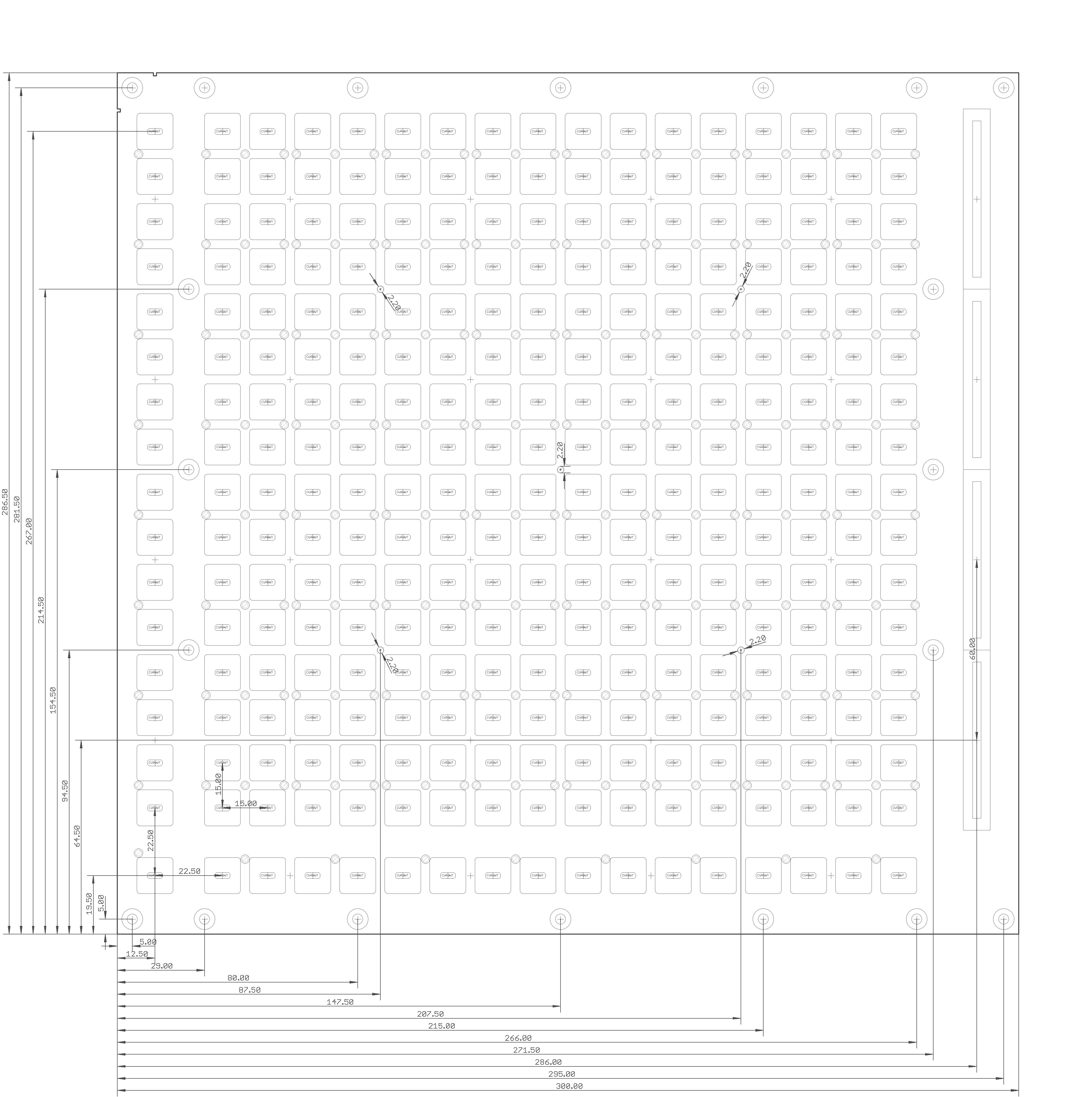
Dimensions
Here are the dimensions for the button, hole and slider locations. Note that the unmarked mounting holes are M3 (3.2mm diameter)
