This is an old revision of the document!
Table of Contents
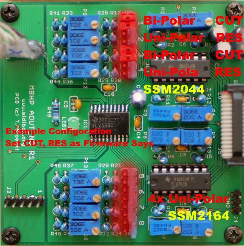
ssm2164_seppoman pcb introduction
seppomans building information;ssm2164_pcb
the following informations are take from the midibox forum, its a collection of infos, without the claim to be 100% true, i will try to test the given information.
Power
+ GND -
J5 is obviously the only connector where you could come to the conclusion that it might have something to do with power supply.Just like the:
AOUT(NG), the 2044 board, the MB_FM module etc, it expects a bipolar power supply of +/- 12 V and GND.
CV
as a general rule of thumb you can assume that everything that doesn't specifically mention a bipolar control voltage will expect an unipolar CV.
In the case of this module, IIRC the dynamic range of the regular CV range (0 .. 11.67V) (uni-polar!) is about 65 dB, with 0V being “silence” and 11.67V being unity gain.
I have never thought about what happens if you apply a negative voltage to the CV input…
Note also that generally a bipolar control voltage (CV) still doesn't mean that there are more than two wires involved,
just the one signal can be above or below GND.
AOUT_NG Connect and Setup
AOUT_NG Stuffing Parts PCB
Resistor Solution stock - very low voltage
if you followed aout_ng built plan you will get following Stock-CV-Voltages @+-12V PSU:
Uni-Polar CV-Range: 0-11,4V
Bi-Polar CV-Range: +-3V
SSM2164 & Stock AOUT_NG:
As the SSM2164 is UniPolar, and seppoman designed it as a couple with AOUT_NG. stock is ok
SSM2044 & Stock AOUT_NG:
As the CUT-Off-CV is UniPolar, and seppoman designed it as a couple with AOUT_NG. stock is ok
I guess for proper +/- 5V operation I'll have to try out a few other resistor values on the SSM module,
but this will only apply if you if you're using a different CV source than an AOUT_NG.\\
If you need more CV-Range:
for more distortion, drive, range, or other modules:
if you sum two voltages through two resistors of same value, you'll get (V1+V2) / 2 as a result…
Resistor Solution low voltage - seppomans prefered
R9…R16 > 5.6k (only on the channels that are setup for bipolar mode)
+-3.5V to +-5.8V Bi-Polar calibration range
Pro: easy job, still have a decent precision when calibrating.
Con: “just change the jumpers if you need some channel in bipolar mode” thought will not work. (
Resistor Solution Stock - -5V Level shifter - NorthernLightX prefered
we came to the conclusion that it's probably much easier to have the AOUT only output unipolar 0 to 10 volt, and design a simple -5v level shifter board that can be used as an add-on (or separate module with hands-on access to the level shifting) to shift the output to -5 to +5 volt where needed.
Things to consider are:
- not a lot of equipment actually makes use of negative voltages
- equipment that needs bipolar CV input can be retrofitted with a fixed level shifter at the input to make it compatible with your other modules
- negative voltages can be used for CV modulation purposes (modulate one CV source with another) so it's certainly not useless
Resistor Solution high voltage
R1…R8 > 10k
R9…R16 >2.2k (on all channels). (QUESTION WHY ON ALL? 
+9.5V to +22V Uni-Polar calibration-range
+-2.4V to +-5.5V Bi-Polar calibration-range ( dont think so 
Pro: preserve the “just change the jumpers if you need some channel in bipolar mode” thought behind this option.
Con:dramatically increase the calibration range, i.e. exactly calibrating the outputs will get harder because the same angle of turning the pot will have much more impact.
MODs
MODE Resistor - Noise vs Distortion
SSM2164 Pin 1 (the first pin) sets the “Mode”
Class AB
Pin is Open, no Resistor to +12V (PCB Default)
Lower current results in higher distortion/lower noise.
Class A
Pin is Connected to +12V via a Resistor
Higher current results in lower distortion/higher noise
lets look in the datasheet:

Figures 11 and 12 show the THD and noise performance of the
SSM2164 as the bias current is adjusted. Notice the two
characteristics have an inverse characteristic.
The quiescent current in the core is set by adding a single
resistor from the positive supply to the MODE pin. As the
simplified schematic shows, the potential at the MODE pin is
one diode drop above the ground pin. Thus, the formula for the
MODE current is:
I
MODE
=
(
V
+
)
−
0. 6
V
R
B
With 15 V supplies, an RB of 7.5k gives Class A biasing with a current of 1.9 mA. Leaving the MODE pin open sets the SSM2164 in Class AB with 30 μA in the Gain-Core

