Before you start fingering with your newly ordered parts there is one important thing to remember. These things are very fragile, especially when it comes to electricity. This means that even static electricity from your fingers may damage your components! Pots, buttons and such are not that fragile, but a PIC may easily die on you because of some stupid carpet on the floor (trust me). To reduce the risk of this happening you should ground yourself at all times while working with the parts. There are special made bracelets out there for this, but a wire will work too. Just connect it to the grounded pin in your power outlet. Just remember not to miss the pin, hit both holes at once and kill yourself :)
When I buildt my box i decided I wanted both a MIDI In and MIDI Out indicator LEDs, not just the one featured on the PCB. I used the schematics from the MIDIBox Plus as a base and made a small circuit that connects to the RX and TX pins of the PIC. I still haven't finished this circuit because I'm missing some parts, but when I do I'll put it here on the page. In the meantime, or if you only need one midi activity LED, use the feature already on the PCB.
I would love to give you a complete guide on how to solder, but fact is, I don't know shit about soldering. Only thing I know is that if you're good it's possible to make a soldering stand extreme heat and even an earthquake, but that anyone can make a wire stick to another with some tin and that's plenty enough for me! If you need some basic soldering-info try these links and get back when you're ready for the ultimate test, a MIDIBox PCB :)
EPE "Basic
Soldering Guide"
A soldering
tutorial for the mechanically challenged
![]()
Okey, now you're ready for the test. The PCB is mounted and you've got all the tools you'll need for the job (ask around at schools and such). Remember, you solder on the side where the metal is, the components go on the green side.
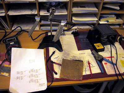
My setup. A tool for
mounting the PCB is nice.
The basic rule is that tallest components go last. This means that we'll start with the bridges. Bend them and solder away. For now there is no worrying about overheating or something, so take the opportunity to test your skills here. When the bridges are done go for the resistors (the coloured small candy-like components). These are not very heat fragile either, but don't overkill either. You might end up with a small problem when you're up for the "resistor array" around the button connection points. Just bend the resistors like on the picture and everything will be fine.
This' the way, aha
aha...
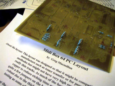
Your PCB should look something like this now.
Okey, now we're ready for the sockets (you did order sockets didn't you?). Be careful when you bend the pins and then solder them into their right positions.
Next thing up is the capasitators. Now, these come in two flavours. The ones where directions does count (electrolytic) and the ones where it doesnt. The polarity is usually printed on the capasitator, one pin is - and one pin +. Measure with the multimeter on "beeper" and make sure the + side of the capasitator is soldered to the side where + comes in.
Now we'll do the two diodes. These are side-spesific too and be a bit carefull with the heat. The line on the diode should be at the end where the - is (see the PCB layout).
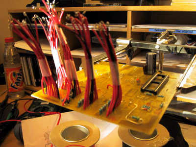
Now you should have
something like this, except for my home-made flexicables.
Also there should be more sockets on your board.
What's left now is the transistor, the voltage-regulator and the crystal. The voltage-regulator goes straight on. The transistor too, but watch out with the heat. Now, the crystall should be soldered on the opposite side of the board (the same side as you've been soldering (where the metal is). This is to shield it. Put the legs into the holes but leave some room so you can bend the crystal to the surface later on. Also a bit of room makes it easier to solder it onto the PCB.
Tha'ts it,
you're done! Only thing left is to solder the wires from
the pots/buttons to the board and to insert the ICs into
the sockets, but we'll do that later. If you've got some
kind of flexicable socket you should solder them to the
board now.
![]()
Copyright © 2001
Tor Arne Vestbø