The easiest way to solder all the pots and the buttons is to mount them to the panel first. This way you can measure exactly how long the wires need to be, and besides, soldering all them pots and buttons and then mounting them can be quite a hassle, believe me. Just be careful not to touch any of the wires with the soldering iron as this will damage the wires and also produce a strange, but yet intriguing, smell.
Each pot has 3 contact points. One should be connected to +5V, one to ground and the last one to the respective IC. Most pots work in a way that when you turn the pot all the way to the left (anticlockwise) you turn it against the pin that should be connected to ground. When you turn it all the way to the right (clockwise) you turn it against the pin that should be connected to +5V. Between these two pins is the pin that goes to the IC. The pots can share the grounding and the +5V (connected in parallel) , but not more than 8 pots at a time or else the last pot won't get the same voltage as the first. Now bundle 8 and 8 pots like one the picture below.
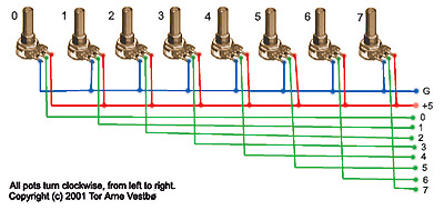
Remember, no more than
8 pots in a bundle.
This way, when you turn a pot, it will send out a controller-value from 0 to 127, not from 127 to 0. Although if the opposite happens than just switch the ground and the +5V wire and you'll be fine.
If for some reason you start measuring the pots with your multimeter and discover that when your pots are connected they no longer go from 0W to 10KW, but from 0W to ca 3KW and then to about 1,25KW this has a simple explanation. There are 8 pots, all at 10KW. Divide these two numbers and you can see a pattern. Just relax, the PIC will compensate for this change in W. Everything is the way it's supposed to be!
Remember that
there is one single pot for the LCD which has it's own
connection point on the PCB so don't include this with
the other pots.
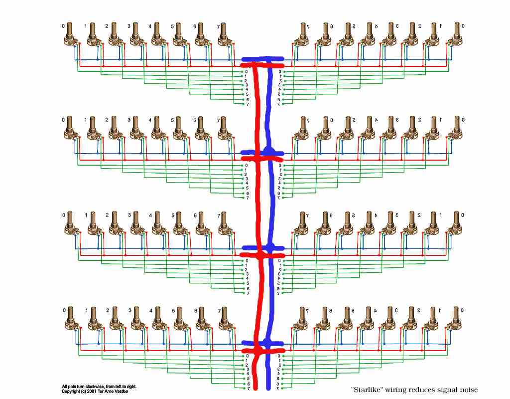
Thorsten advices that in order to reduce signal noise, you should
wire the ground and +5V cables in a "starlike" fashion. The chassis
should also be connected to ground.![]()
Buttons come in many different variations. We want the ones who doesn't stay in when pushed, but returns back out, ready for another push. They also come with various number of pins, but just put your multimeter on "beeper" and find two pins that are silent when the button is not pushed and beeps when pushed. There you have your two pins. The connection works just like on the pots, apart from that there is no voltage input. Just one ground pin and a "send"-pin that goes to the IC. Select one of the pins to be ground and be consequent about it. Hook all the ground pins together and end in one wire like with the pots. Then solder a wire to each "send"-pin and bundle like with the pots (8 in a bundle).
Copyright © 2001
Tor Arne Vestbø