Not very hard really, as long as you haven't got a 1mm distance between each pin like I had on my LCD. Be careful with heat. Solder a flexicable or wires to the LCD so it'll be easy to connect to the PCB later on.
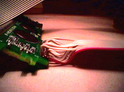
Thorsten had so solder
the LCD for me, and as you can see he's
an expert in handling small parts.
![]()
All the LEDs have one "+" and one "-" pin. They way to see which is which is to study the LED closely. You can see that one of the pins end in what looks like a cup or a hand inside the LED. This is the "-" side. On each LED (except for the MIDI activity and power led) the "-" pin is connected to ground trough a 220W resistor. This is not included on the PCB so you have to solder the resistor to the LED. The best way to do this is to tie together one leg of the resistor and one leg of the LED with one of the small wires you find inside a normal wire.
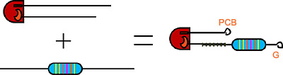
Amazing what you can do with maths these days isn't it?
![]()
Of course we're going to need power to our box. You should use an external adapter which converts from the AC voltage in your wall outlet to the correct DC voltage for our box. These are the recomended data for the adapter:
Voltage range: 7-9V
Current: 500mA or more
It is possible to use AC to AC adapters, but then you'd have to solder in some extra components not featured on the PCB. In that case the recomended voltage range is 8-10V.
You can connect the adapter straight to the PCB but I added some components in between. This is my setup:
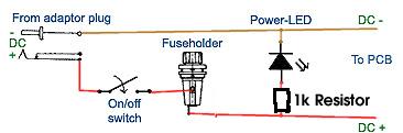
Okey, the LED is
upside down, but you get the picture?
![]()
Copyright © 2001
Tor Arne Vestbø