You should find a way to mount the PCB inside the case before you start. This can be done with screws or maybe tape just for the testing. Leave all socket mounted components (ICs and PIC) in their bags for now and turn on the power. Use your multimeter to measure that you get +5V only where you're supposed to! If there are any short circuits these should be fixed before proceeding!
Okey, now we're ready to connect the PCB to our other parts. Be careful at all times not to short circuit your PCB, which may cause damage to your components. Insert the PIC into it's socket and connect your MIDI cables and LCD like on the pictures below.
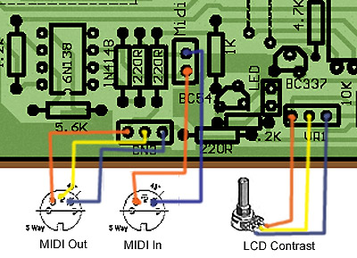
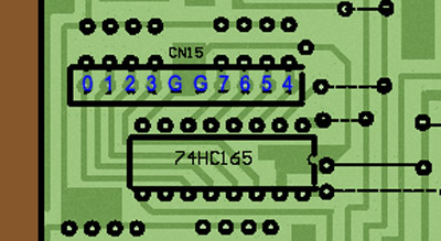
Some essential parts
to connect before testing!
Make sure you get this
right or else the PIC will halt at boot time.
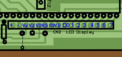
Now flick the power button and use MidiOx to log your incoming MIDI events. If everything's working you should see your screen fill with MIDI messages. This is because the PIC is receiving lots of random voltages which it believes to be MIDI controller messages. In the LCD you should now see a menu (if it's blank try your contrast pot).
If nothing happens try to unconnect the LCD and put a pulldown-resistor (10K) between pin 40 of the PIC and ground. If you now get MIDI messages in MidiOx you have a problem with your LCD which causes the PIC to halt at boot time.
Okey, the PIC is obviously working and the LCD is fine. Time to connect the pots. Make sure the power is off and connect each 8-pot bundle like below.
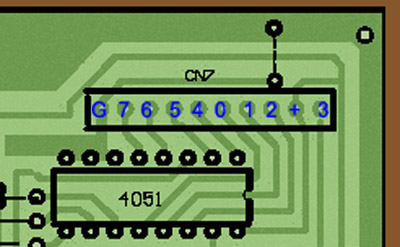
Don't mix up ground
and +5V or else your pots will turn the wrong way.
Then connect the LEDs like this:
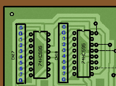
You have two ground
points here for some reason, never mind that, choose one.
Last up is the buttons, they go a little something like this...
Two ground points here
too, but again, never mind :)
Okey,
everything's connected now. Time for the real test. Power
up and go berserk with the pots. If MidiOx gives you info
as expected you're a hero, if not go back and check
everything. Use your multimeter to measure each pot and
button bundle and so on. The truth is out there...
![]()
Copyright © 2001
Tor Arne Vestbø