tm5-dindoutgate
Table of Contents
TM5-DinDoutGates
it gives;
24 Digital Inputs
32 Digital Outputs
* while 16 Outputs are used for UI
* the other 16 are buffered, and are for use as 16 GAte/Triggger output at 5V Level
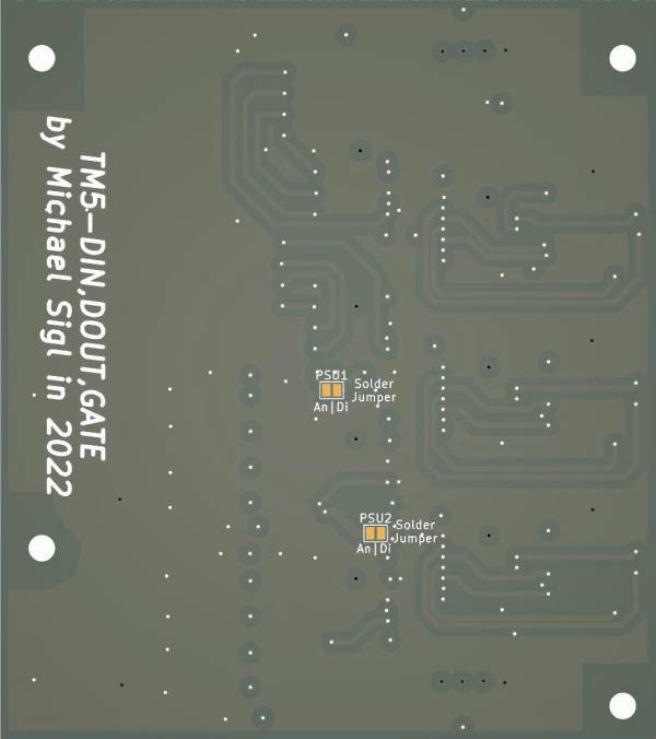
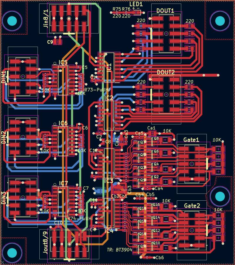
The Board is fully SMD, and made for pick and place - so no soldering required!
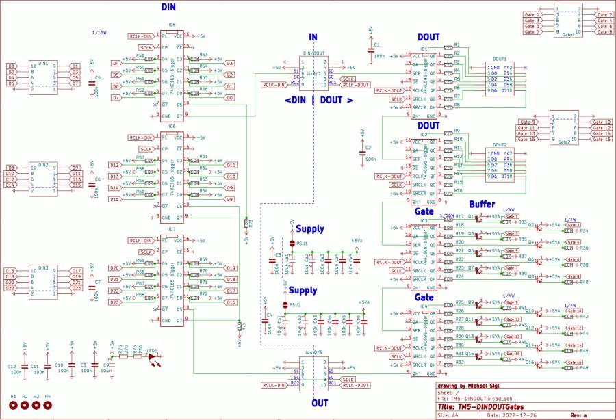
Shematic
Building and BOM
Its build by pick and place robots… so no need to build, or order any component
you need this PCB 1x for triggermatrix5
BOM
Follwing list is for reference, and debugging only, no need to order them! all the parts are already soldered on the PCB!
| qty | reference | value | footprint | jlc |
|---|---|---|---|---|
| 18 | C1 – C12, Ca3, Ca4, Ca5, Cb3, Cb4, Cb5, Cb6 | 100n | C_0402 | C307331 |
| 5 | C9, Ca1, Ca2, Cb1, Cb2 | 10uF | C0805 | C440198 |
| 5 | DIN1, DIN2, DIN3, Gate1, Gate2 | Gates | Pin-Head-10-SMD | C124391 |
| 4 | DOUT1, DOUT2, Jin8/1, Jout8/9 | DIN/DOUT | Pin-Head-10-SMD | C124391 |
| 4 | IC1, IC2, IC3, IC4 | 74HC595-bigger | HC595-smd | C5947 |
| 3 | IC5, IC6, IC7 | 74HC165-bigger | HC165-smd | C5613 |
| 1 | LED1 | LED | LED-0603 | C2286 |
| 16 | Q1 – Q16 | MMBT3904-7-F | MMBT3904-7-F | C20526 |
| 16 | R1 – R16 | 220 | R_0805 | C25294 |
| 42 | R17 – R74 | 10K | R_0402 | C25744 |
| 16 | R33 – R48 | 10K | R_1206 | C17902 |
| 2 | R75, R76 | 220 | R_0402 | C25091 |
To Do
waiting for the assembled Prototype
Community users working on it
- Phatline = PCB & Shematic, UI-Programming, Documentation…
Just let a Private message on the forum to user already involved.
or join the forum: Triggermatrix 5
tm5-dindoutgate.txt · Last modified: 2022/12/28 19:57 by phatline


